
Transfer molding method, transfer molding device, and molded article

a technology of transfer molding and molded articles, which is applied in the direction of applications, manufacturing tools, other domestic articles, etc., can solve the problems of complex devices, deterioration of the flowability of resins when injected, and further complicated devices, so as to achieve efficient and accurate molding and simple mechanisms

Inactive Publication Date: 2015-11-19
CANON KK
View PDF4 Cites 5 Cited by
  • Summary
  • Abstract
  • Description
  • Claims
  • Application Information

AI Technical Summary

Benefits of technology

The present invention provides a method and device for transfer molding thermosetting resin components in a simple mechanism. It involves sequential primary and secondary molding to efficiently and accurately join multiple divided bodies. This method and device can effectively mold layered components and produce molded articles with high efficiency and accuracy.

Problems solved by technology

Further, as for a molded article requiring high dimensional accuracy, since a large amount of filler having a small line expansion rate such as silica is included in a resin, flowability of the resin is deteriorated when it is injected.
Further, even though the runner for the primary molding is disposed on an abutment face of each die to avoid the breakdown cleaning of the die, since the different runners between the primary molding and the secondary molding are used, the resin needs to be injected from a plurality of points, thereby making the device complicated.
There is a problem in which the device becomes further complicated to mold a layered component of the divided bodies including three stages or four stages.
However, with this method, there is a problem in which, since the divided bodies are released from the die once, positioning of the divided bodies to be joined with one another is difficult and, in addition, a dimensional accuracy is hard to be realized due to warpage of the divided bodies.

Method used


Image

  • Transfer molding method, transfer molding device, and molded article
  • Transfer molding method, transfer molding device, and molded article
  • Transfer molding method, transfer molding device, and molded article

Examples


first embodiment

[0049]With reference to drawings, a transfer molding method, dies, and a molded article according to a first embodiment of the present invention will be described below.

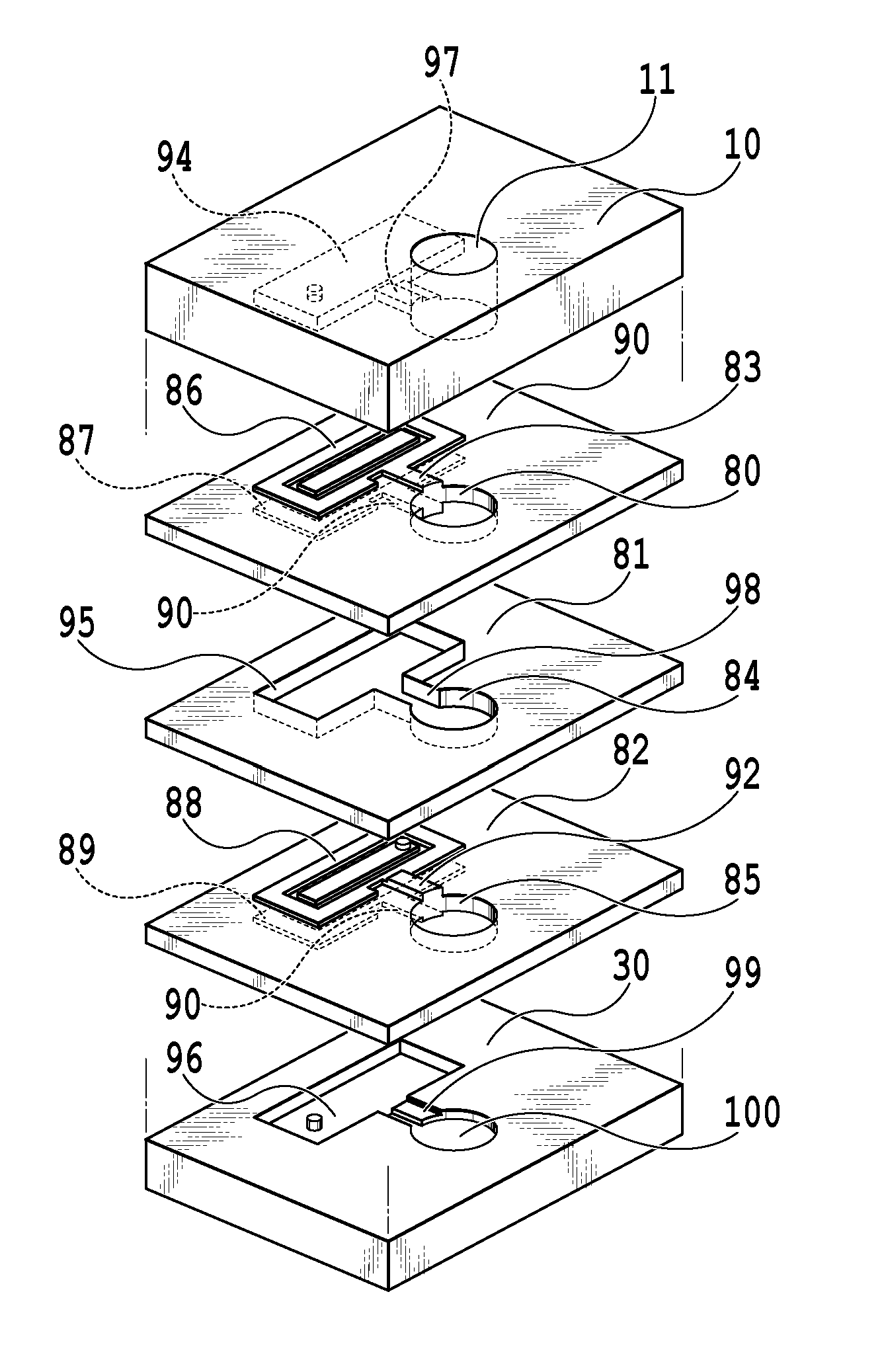
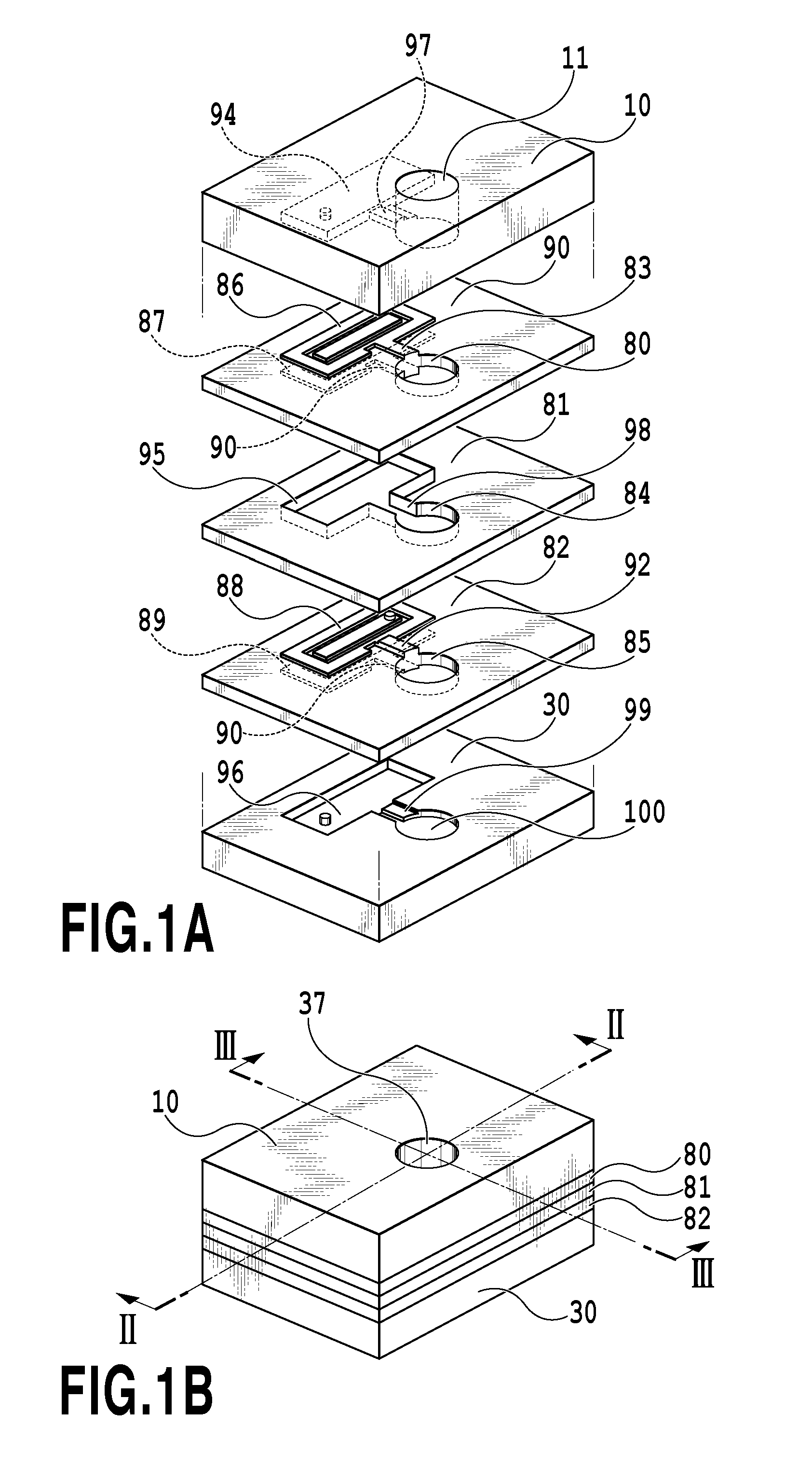
[0050]FIGS. 1A, 1B illustrate the dies to which the first embodiment can be applied. FIG. 1A is an exploded perspective view of the dies, and FIG. 1B is a perspective view of the clamped dies. A transfer molding die includes an upper die 10, a first intermediate die 80, a second intermediate die 81, a third intermediate die 82, and a lower die 30 which can be each layered as illustrated in FIG. 1A. The upper die 10 includes a first chamber 11 via which a thermosetting resin (molding material) is poured, a first groove 97, a first cavity 94 that is a portion to be one layer of a layered component. The first intermediate die 80 includes a second chamber 83 formed sequentially from the first chamber 11 of the upper die 10, and further includes a first core 86 and a first fitting portion 90 at an upper die side, and a se...

second embodiment

[0076]With reference to drawings, the second embodiment of the present invention will be described below. Since a basic configuration according to the present embodiment is similar to that of the first embodiment, only discriminative configurations will be described below.

[0077]FIGS. 12A, 12B are cross-sectional views of the second embodiment of the present invention. FIGS. 12A, 12B are cross-sectional views each illustrating a process of the first primary molding. FIGS. 13A, 13B are cross-sectional views each illustrating a process of the second primary molding. FIGS. 14A, 14B are cross-sectional views illustrating each process of the secondary molding. According to the present embodiment, the primary molding is performed using two transfer molding devices.

[0078]As illustrated in FIG. 12A, a first transfer molding device 134 performs the primary molding to mold a first divided body 51 and a second divided body 52 in two cavities partitioned by the intermediate die 20 using three di...

third embodiment

[0082]With reference to drawings, the third embodiment of the present invention will be described below. Since a basic configuration according to the present embodiment is the same as that of the first embodiment, only discriminative configurations will be described below.

[0083]FIGS. 15A, 15B illustrate dies to which the third embodiment can be applied. FIG. 15A is an exploded perspective view illustrating the dies on which the primary molding has been performed and the secondary molding is being performed. FIG. 15B is a perspective view illustrating the dies that have been clamped. FIG. 16 is a cross sectional view taken along the line XVI-XVI illustrated in FIG. 15B. FIG. 17 is a cross-sectional view taken along the line XVII-XVII illustrated in FIG. 15B and illustrates a state where the thermosetting resin 70 is poured in the secondary molding.

[0084]As illustrated in FIG. 15A, according to the present embodiment, a communication path (communication portion) 25 for communicating t...


PUM

PropertyMeasurementUnit
temperatureaaaaaaaaaa
thermosettingaaaaaaaaaa
pressureaaaaaaaaaa

Abstract

Provided are a molding method for efficiently and accurately performing molding of a layered component made of a thermosetting resin by a simple mechanism, and molded articles. For this purpose, primary molding for molding a plurality of divided bodies and secondary molding for joining the plurality of divided bodies with one another are performed sequentially.

Description

BACKGROUND OF THE INVENTION[0001]1. Field of the Invention[0002]The present invention relates to a transfer molding method and a transfer molding device that mold a hollow molded article with a thermosetting resin, and to a molded article.[0003]2. Description of the Related Art[0004]Heretofore, as a method for molding a hollow component by an injection molding method, a method is known which molds a divided body by primary molding, and makes a plurality of divided bodies abut on and join with one another by secondary molding. For a molding device, a die sliding system is known for sliding a die between the primary molding and the secondary molding. Further, a system (Japanese Patent Laid-Open No. H11-042670 (1999)) is known in which a divided body is molded with an intermediate die sandwiched between a lower die and an upper die (primary molding) and, subsequently, the intermediate die is released to make the lower die and the upper die abut on each other so as to perform molding (s...

Claims


Application Information

Patent Timeline
Patent Type & Authority Applications(United States)
IPC IPC(8): B29C45/02B29C45/26B32B27/38B32B3/30B32B27/08B29C45/16B32B3/26
CPCB29C45/02B29C45/16B29C45/2624B32B3/266Y10T428/1352B32B27/08B32B27/38B29K2063/00B32B3/30B29C33/0088B29C45/14467B29C45/2602B29K2105/16
Inventor KAWAMURA, SHOGO
Owner CANON KK
Learn More