Operating mechanism for tank car bottom valve

Active Publication Date: 2015-11-26
GUNDERSON
View PDF17 Cites 5 Cited by
  • Summary
  • Abstract
  • Description
  • Claims
  • Application Information

AI Technical Summary

Benefits of technology

The invention is a way to make sure that the parts of a machine are connected securely, but can easily disconnect if there is a sudden bending force or lateral force applied to them. This prevents damage to the machine and ensures that it operates safely and efficiently.

Problems solved by technology

Nevertheless, there has been some danger in the past that a bottom valve operating mechanism might open the bottom valve if a derailed car encounters the ground or other obstructions in such a way that the valve operating mechanism is affected.

Method used


Image

  • Operating mechanism for tank car bottom valve
  • Operating mechanism for tank car bottom valve
  • Operating mechanism for tank car bottom valve

Examples


Embodiment Construction

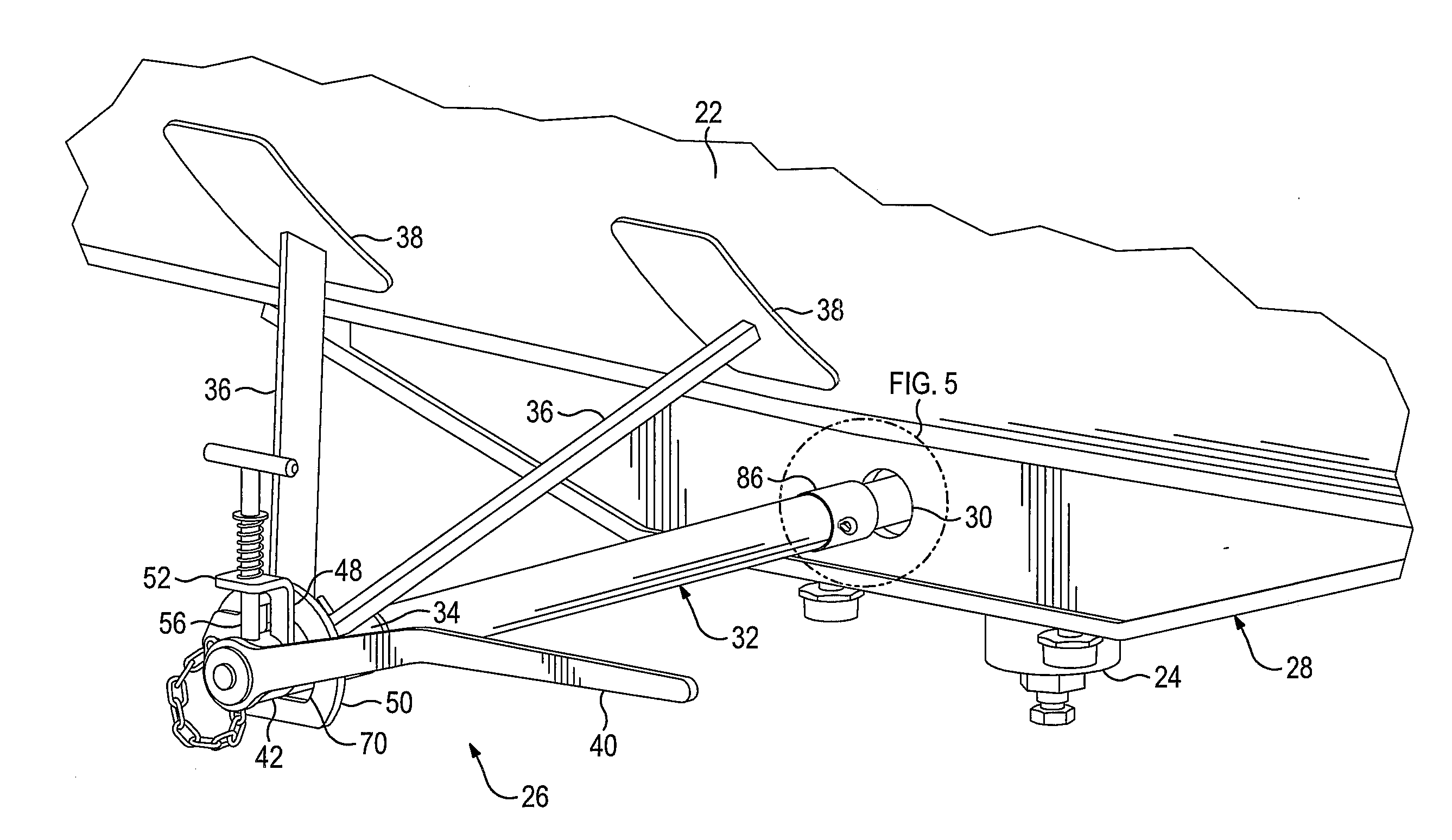
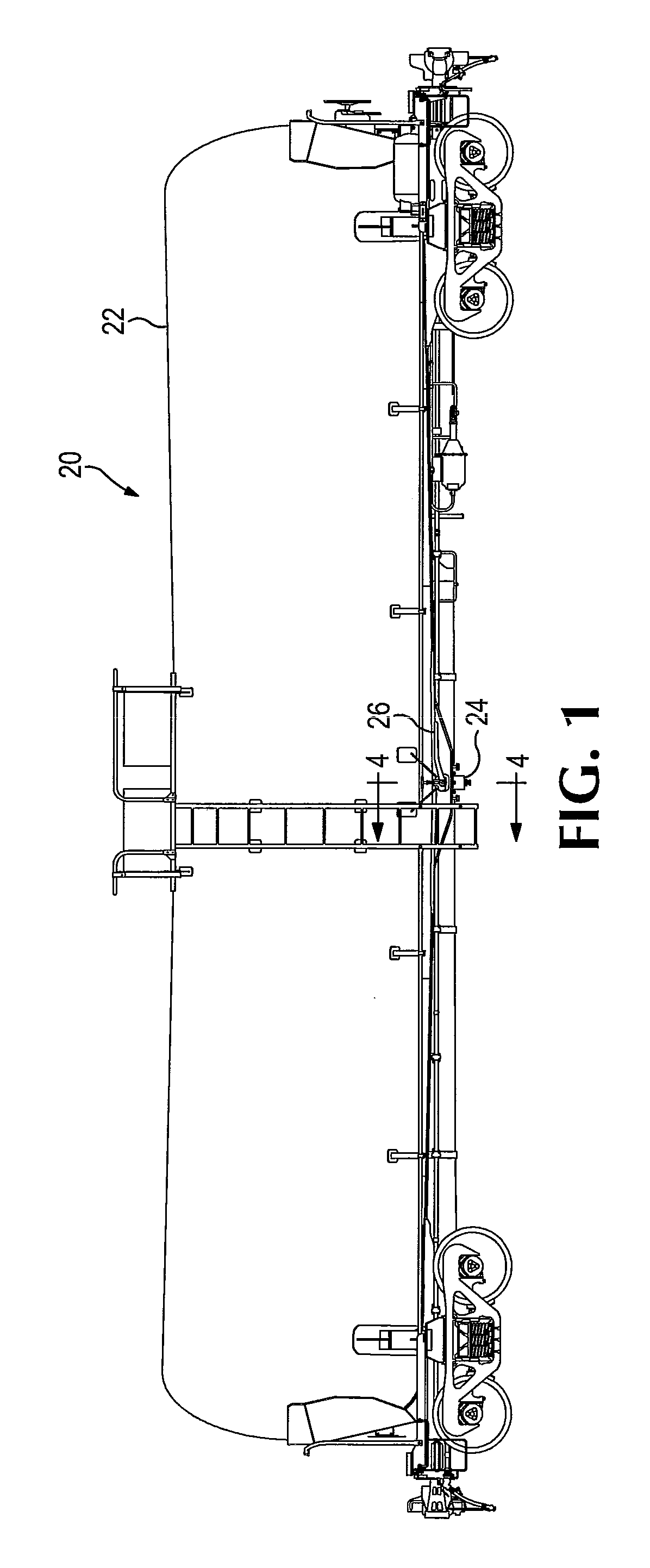
[0033]Referring now to the drawings and photographs which form a part of the disclosure herein, a railroad tank car 20 shown in FIG. 1 has a body that includes a cargo tank 22 having a bottom valve 24 centrally located along the length of the tank car. The bottom valve 24 is operable by a valve-operating mechanism 26 that extends laterally from the bottom valve 24 to a position spaced laterally outward from the centerline of the tank car in order to be conveniently operable in connection with unloading the car.

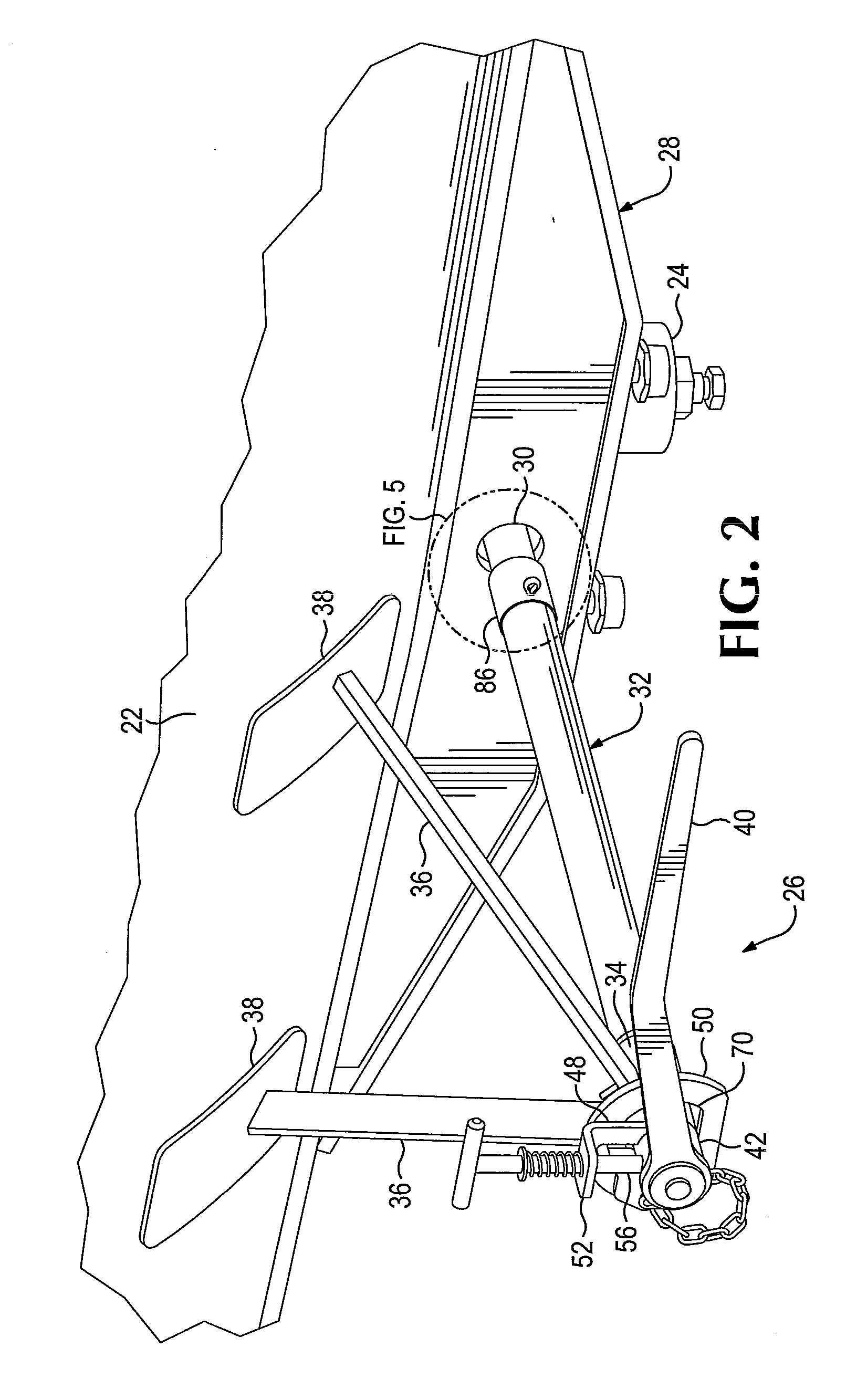
[0034]As shown in FIGS. 2, 2A, 3, 3A, and 4, the bottom valve 24 is protected by a surrounding protective structure 28 which may include a substantial wall of steel plate construction defining a hole 30 through which a valve operating shaft assembly 32 extends laterally outward from the centerline of the tank car. The valve operating shaft assembly 32 extends outwardly to a support bearing 34 which may be a sleeve surrounding the valve operating shaft 32 and may be supported b...


PUM


Abstract

An operating mechanism for a bottom valve for a cargo tank of a railroad tank car, in which a valve operating lever is normally disconnected from a valve operating shaft and a valve operating shaft assembly includes a weak-link connector to prevent inadvertent opening of the bottom valve in case of derailment of the tank car.

Description

BACKGROUND OF THE INVENTION[0001]The present invention relates to railroad tank cars, and in particular, to an operating mechanism for a valve controlling release of liquid cargo from the bottom of a railroad tank car.[0002]A bottom valve in a railroad tank car is used to drain liquid cargo from the car. Such a valve is located near the lowest point in the cargo tank, usually near the center of the length of the car, between the wheeled trucks that support the car on the rails. Such a valve is usually provided some protection, such as by a substantial structure at least partly surrounding the valve, in order to reduce the danger of release of liquid cargo should the car be derailed. Nevertheless, there has been some danger in the past that a bottom valve operating mechanism might open the bottom valve if a derailed car encounters the ground or other obstructions in such a way that the valve operating mechanism is affected.SUMMARY OF THE INVENTION[0003]An operating mechanism for a bo...

Claims


Application Information

Patent Timeline
IPC IPC(8): B61D5/00F16K35/02
CPCB61D5/008Y10T137/6877F16K35/025F16K35/02
Inventor SAXTON, GREGORY J.THOMAS, BRADLEY J.JURVAKAINEN, BRIAN J.
Owner GUNDERSON
Why Eureka
Try Eureka