Container with irremovable closure to facilitate dispensation of contents

Active Publication Date: 2015-11-26
BRADLEY MARK ANTHONY
View PDF2 Cites 7 Cited by
  • Summary
  • Abstract
  • Description
  • Claims
  • Application Information

AI Technical Summary

Benefits of technology

[0027]The present invention thus provides a simple to fabricate container stopper, which can enable satisfaction of security, health and safety requirements that are imposed on all types of businesses as well as increasing compliance with rules and regulations that are seen by some as a hindrance to normal business practice. Additionally, certain industries involved with medical device manufacture, drug manufacture and food production, etc. have additional mandated standards regarding control of fluids with the use of dispensing equip

Problems solved by technology

It will be appreciated that in the attachment of some types of closure, expensive machinery is required to fasten, for example metal flanges to containers, which

Method used


Image

  • Container with irremovable closure to facilitate dispensation of contents
  • Container with irremovable closure to facilitate dispensation of contents
  • Container with irremovable closure to facilitate dispensation of contents

Examples


first embodiment

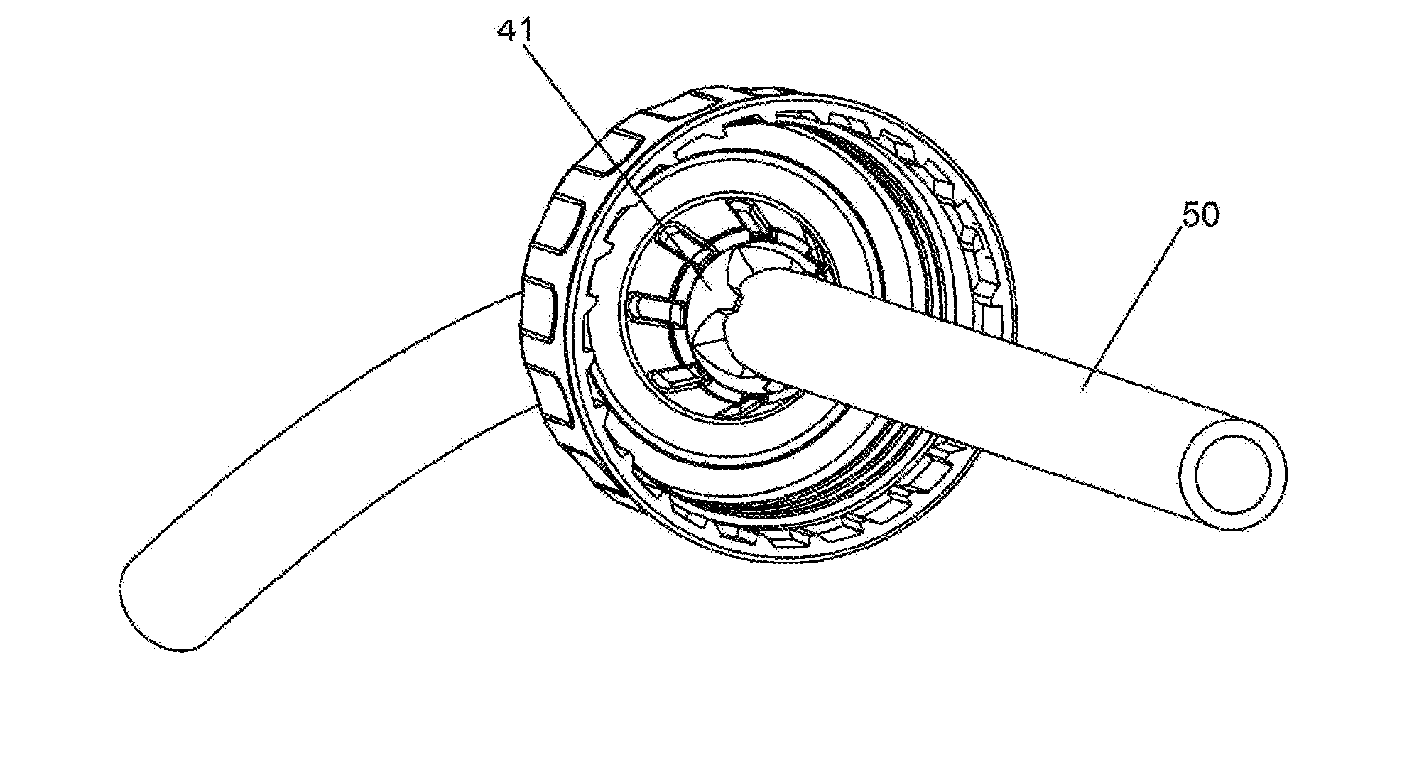
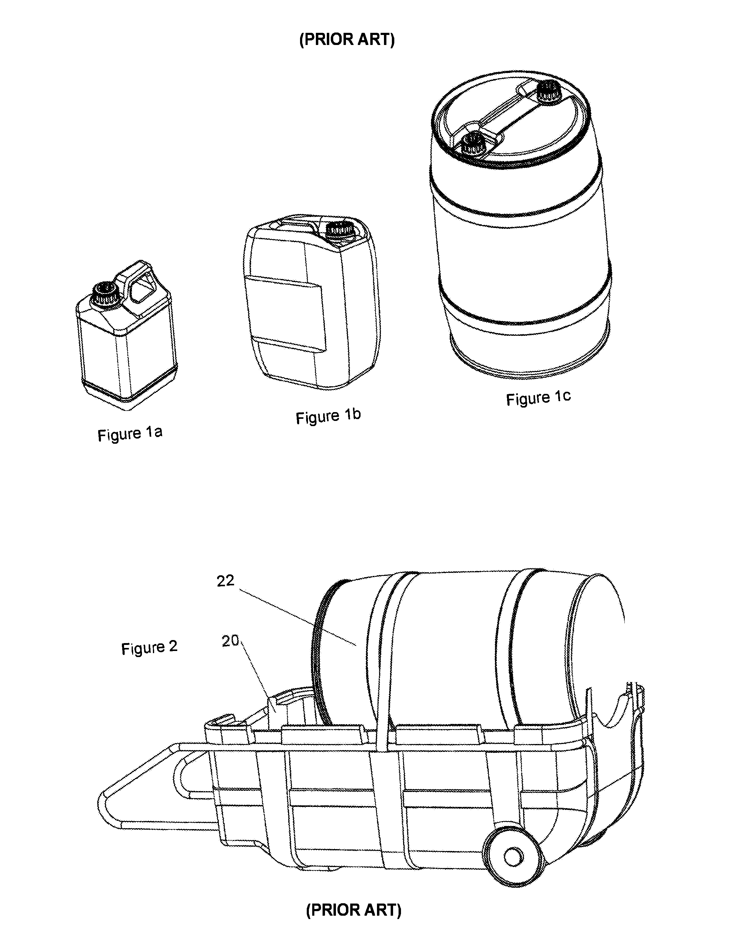
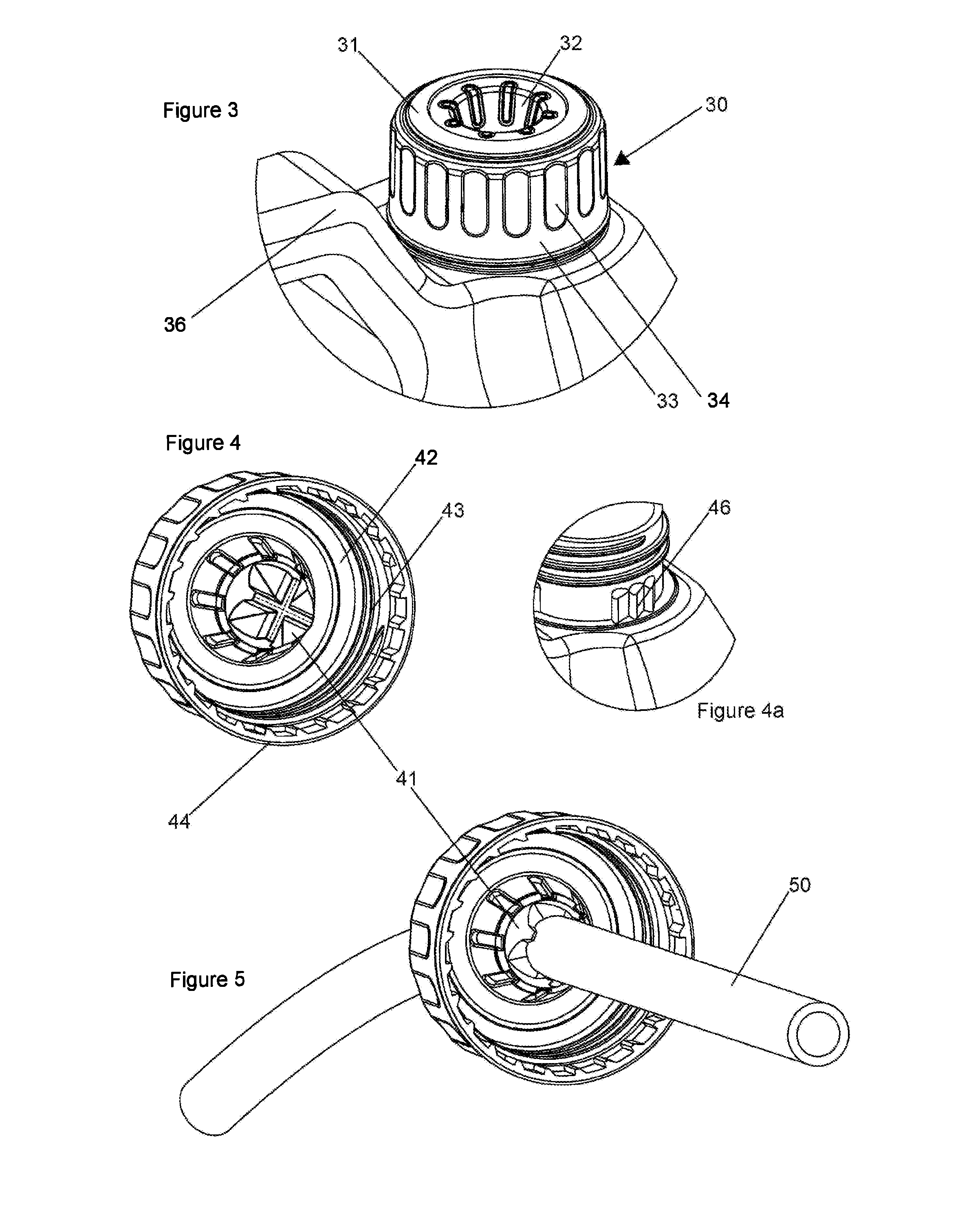
[0056]Referring now to FIGS. 3, 4 and 5, there is shown the invention. Apertured closure 30 is shown affixed to a standard five-liter container 36 as referred to in FIG. 1. The apertured closure has an inside seal member which abuts a rim of the opening of the container. Whilst the rim of the container is not shown, examples of such are well known, typically comprising a short length of generally circularly cylindrical wall about an aperture to the inside of the container, the outside wall having a screw-thread, which is inter-engageable with an inside wall of the apertured closure. Conveniently, the apertured closure 30 has a locking mechanism whereby once attached by way of the screw-thread fittings, removal of the apertured closure is not possible. One-way-detent systems—or barbed systems—are widely available for child-proof caps and the same detent release system can be adapted to ensure that no release is possible. A shroud may also depend from the wall of the apertured closure...

embodiment 220

[0076]In a still further aspect of the invention, a tube and valve combination may be selected to provide an improved seal in use. For example, the tube may be dimensioned to correspond with a general n-flap duckbill valve by having n-super-elliptical portions. FIG. 22 shows such an embodiment 220 having two super-elliptical portions 221, 222 which are dimensioned to achieve liquid flow in the hollow center 226 flow with a maximum degree of sealing as between the elliptical wall portions of the tube 224, 225 and corresponding inside faces of a bi-flap duckbill. It will be appreciated that this design can more effectively seal with respect to the valve or enable the use of less resilient plastics tube for a particular requirement of sealing. The design can extend a tri-, quad-, penta-, etc. stars having Lamé curve elliptical sections to correspond with trifold, quad-fold, penta-fold etc. duckbill seals. With reference to the super elliptic portion 221, this can be described as an are...


PUM


Abstract

A container and closure combination, for the containment of fluids and extraction therefrom by way of an extraction tube. The container comprises a closed volume with an opening configured to close the opening of the container; the closure is provided with an aperture such that the closure, upon fitment to the container opening, cannot be removed therefrom. The aperture of the closure comprises a unitary elastic unidirectional valve member that can operate in a first, closed condition, to prevent a flow of fluid from the container; and a second, operational condition, with an extraction tube sealingly engaged with respect to the valve, to permit an extraction of fluid from the container through the tube.

Description

CROSS-REFERENCE TO RELATED APPLICATIONS[0001]This application is a continuation of PCT patent application serial number PCT / IB2014 / 000208, published as WO 2014 / 118628, titled “CONTAINER WITH IRREMOVABLE CLOSURE TO FACILITATE DISPENSATION OF CONTENTS” and filed on Feb. 3, 2014, which claims priority to GB1301944.3, titled “IMPROVEMENTS IN OR RELATING TO CONTAINER CLOSURES” and filed on Feb. 4, 2013, and to GB1306229.4, titled “IMPROVEMENTS IN OR RELATING TO CONTAINER CLOSURES” and filed on Apr. 6, 2013, and to GB1306672.5, titled “IMPROVEMENTS IN OR RELATING TO CONTAINER CLOSURES, and filed on Apr. 12, 2013, and to GB1311661.1, titled IMPROVEMENTS IN OR RELATING TO CONTAINER CLOSURES” filed on Jun. 28, 2013, and to GB1320532.3, titled “IMPROVEMENTS IN OR RELATING TO CONTAINER CLOSURES” filed on Nov. 20, 2013, the entire specifications of each of which are hereby incorporated by reference in their entirety.BACKGROUND OF THE INVENTION[0002]1. Field of the Art[0003]The present invention...

Claims


Application Information

Patent Timeline
IPC IPC(8): B65D47/06B65D51/16B65D39/00B65D41/06
CPCB65D47/06B65D39/0035B65D51/1644B65D41/06B65D41/20B65D47/36
Inventor BRADLEY, MARK ANTHONY
Owner BRADLEY MARK ANTHONY
Why Eureka
Try Eureka