
Broadcasting system with digital television signals and metadata that modulate respective sets of OFDM carriers

a broadcasting system and digital television technology, applied in the field of broadcasting systems with digital television signals and metadata, can solve the problems of increasing signal overhead, and in-band signaling undesirably complicating demultiplexing of components of the baseband signal

Active Publication Date: 2015-11-26
CERINET USA
View PDF0 Cites 21 Cited by
  • Summary
  • Abstract
  • Description
  • Claims
  • Application Information

AI Technical Summary

Benefits of technology

The invention is a method of transmitting COFDM DTV signals using metadata that includes information about the FFT size, carrier modulation type, and FEC coding type. This metadata is transmitted using scattered modulation of carrier waves in the central portion of the RF channel. The invention also includes a transmitter apparatus that sends these signals and a receiver apparatus that can receive the signals. The technical effect of this invention is the ability to reliably identify and decode COFDM DTV signals using metadata that is transmitted in a scattered manner in the RF channel. This method is useful for DTV receivers in different countries that may use different bandwidth radio-frequency channels or reception standards.

Problems solved by technology

In-band signaling undesirably complicates time-division multiplexing of components of the baseband signal to be up-converted in frequency and then broadcast.
More important, in-band signaling undesirably complicates de-multiplexing of components of the baseband signal in a COFDM DTV receiver.
It is desirable that a number of digital signature sequences can each be readily distinguished from each and all of the others, but this tends to require digital signature sequences quite a few bits long, which also tends to increase signaling overhead, although perhaps to lesser degree than extending the L1 signal or augmenting the L1 signal with in-band signaling that replaces data.

Method used


Image

  • Broadcasting system with digital television signals and metadata that modulate respective sets of OFDM carriers
  • Broadcasting system with digital television signals and metadata that modulate respective sets of OFDM carriers
  • Broadcasting system with digital television signals and metadata that modulate respective sets of OFDM carriers

Examples


Embodiment Construction

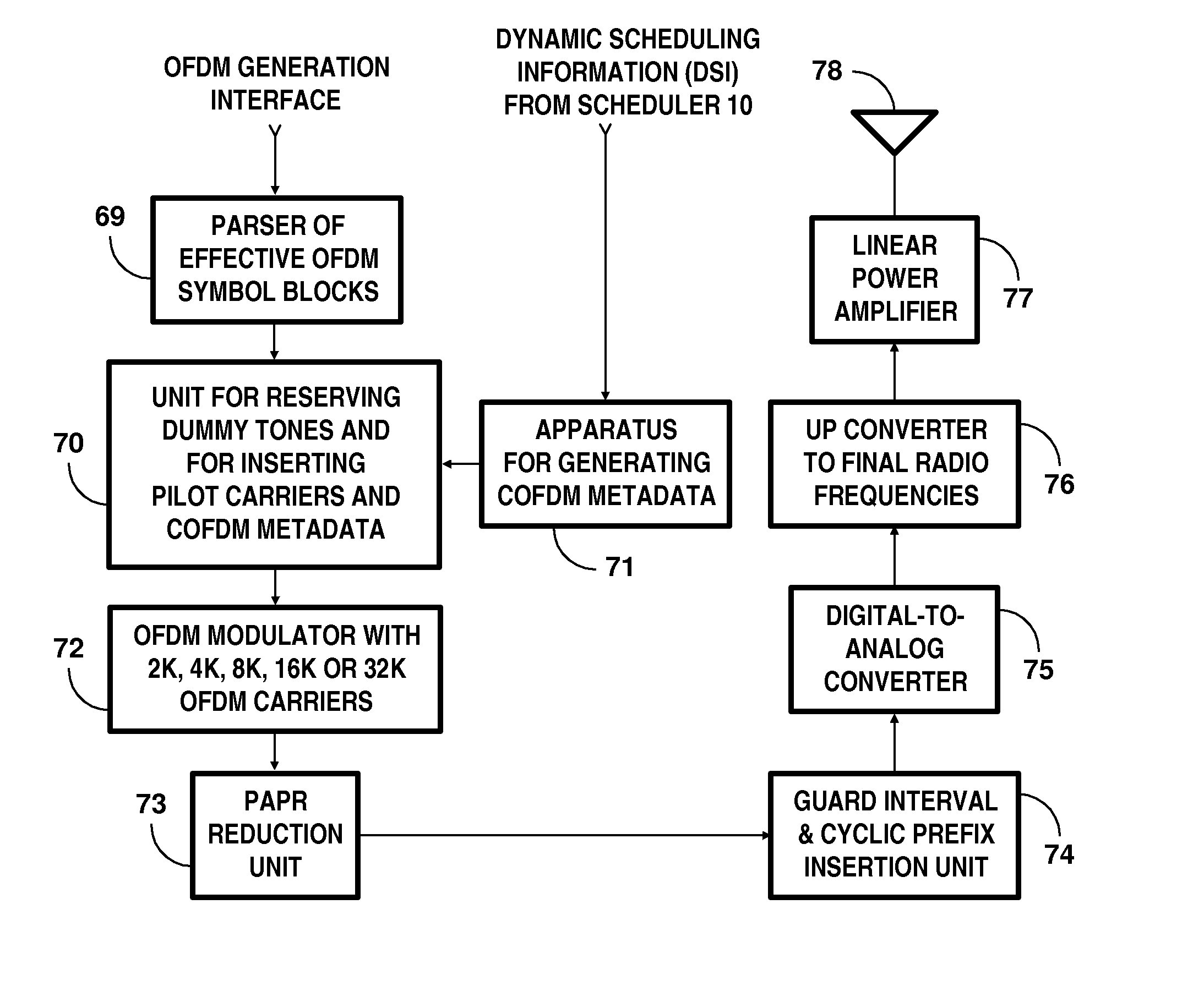
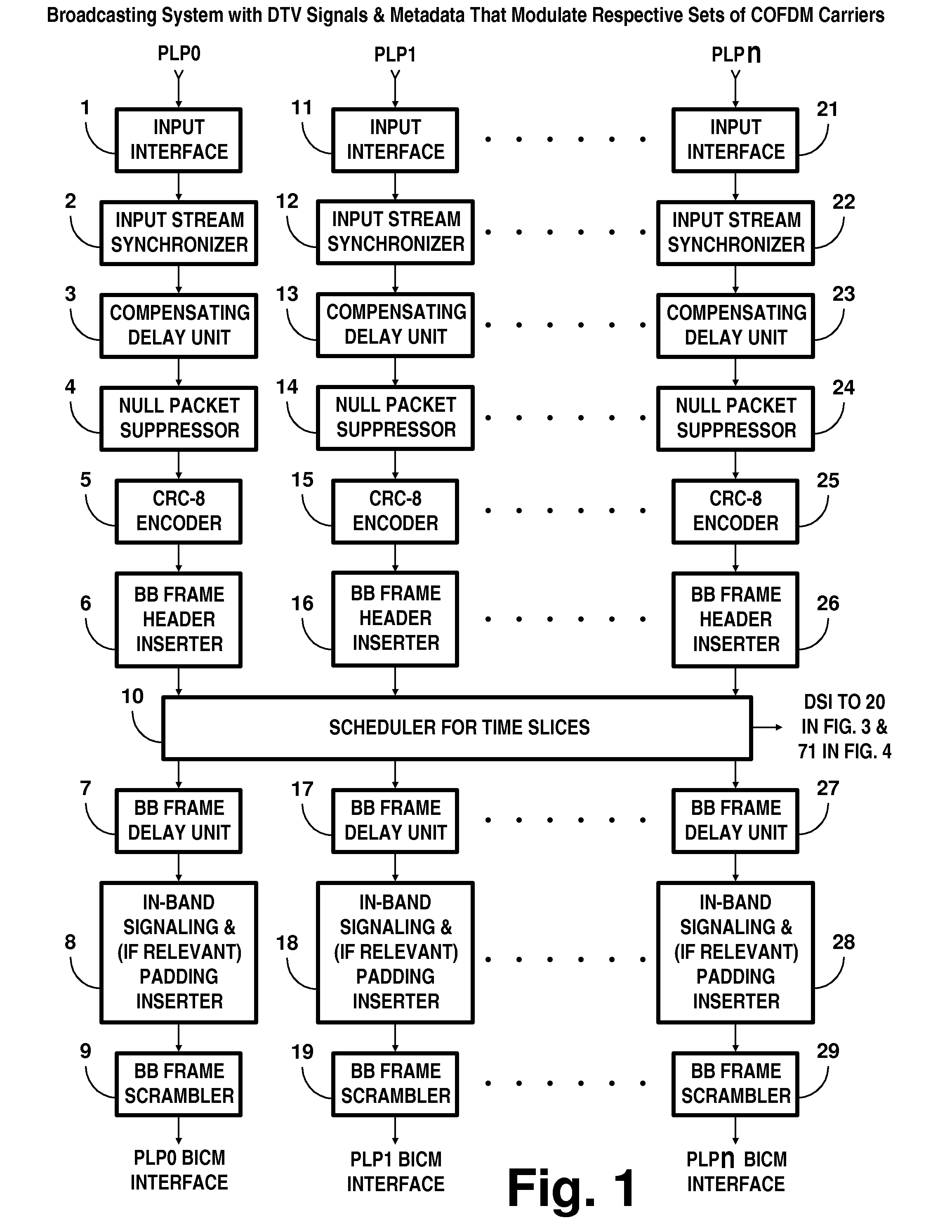
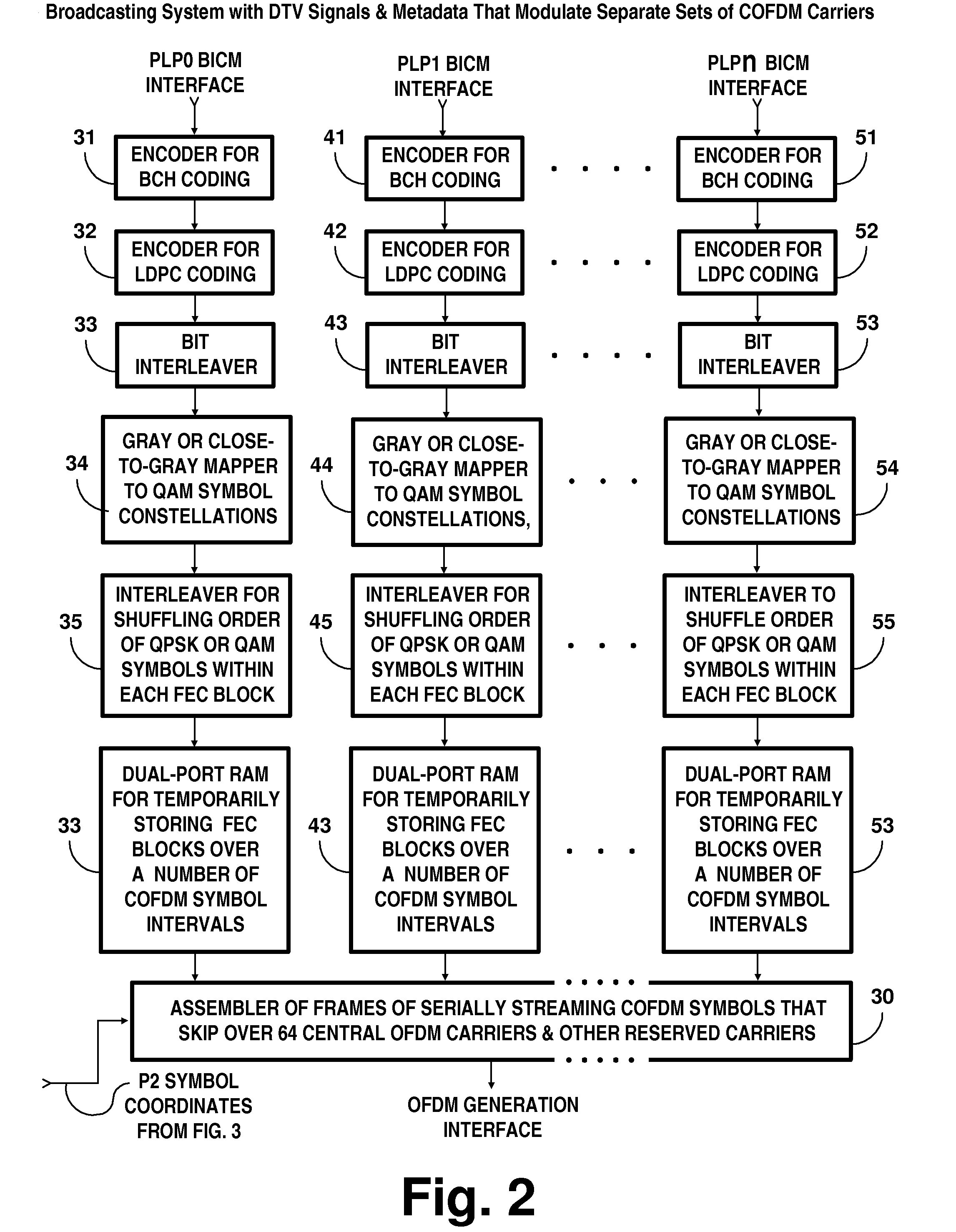
[0028]FIGS. 1, 2, 3 and 4 depict a DTV transmitter apparatus generating COFDM signals designed for reception by DTV receivers. FIG. 1 depicts apparatus for generating baseband frames (BBFRAMES) at a Bit-Interleaved Coding and Modulation (BICM) interface. FIG. 2 depicts apparatus for generating forward-error-correction (FEC) coding and subsequent frames of COFDM symbol blocks responsive to the BBFRAMEs supplied at the BICM interface. FIG. 3 depicts apparatus for generating bit-wise forward-error-correction (FEC) coding and subsequent COFDM symbol blocks responsive to first layer (L1) conformation specifications and to dynamic scheduling information (DSI). FIG. 4 depicts apparatus for generating and transmitting radio-frequency COFDM signals. FIG. 4 further depicts apparatus for inserting baseband metadata including Master Information Blocks (MIBs) into frames of COFDM symbol blocks before subsequently generating and transmitting radio-frequency COFDM signals. Except for the insertion...


PUM


Abstract

Digital television (DTV) broadcasting using COFDM modulation is designed to modulate orthogonal frequency-division-multiplexed (OFDM) mid-band carriers with metadata including synchronization signals and transmission-mode signals. DTV signals modulate OFDM carriers occupying portions of the frequency spectrum of the transmission channel that extend in frequency both below and above these mid-band carriers. The OFDM midband carriers are capable of signaling when a new broadcast service is used that differs from the one disclosed. The signaling is provided by modulating the midband carriers with respective elements of signature sequences, each of which signature sequences is composed of Zadoff-Chu sequences and repetitive pseudo-random sequences scrambled by a Zadoff-Chu sequence.

Description

[0001]This application claims the benefit of the filing date of provisional U.S. Pat. App. Ser. No. 62 / 001,123 filed 21 May 2014. This application also claims the benefit of the filing date of provisional U.S. Pat. App. Ser. No. 62 / 009,457 filed 9 Jun. 2014.[0002]The invention is directed to aspects of a system for broadcasting digital television (DTV) signals using coded orthogonal frequency multiplexed (COFDM) carrier waves.BACKGROUND OF THE INVENTION[0003]Techniques for COFDM DTV broadcasting are prescribed in the ETSI TS 302 755 V1.3.2 Technical Specification titled “Digital Video Broadcasting (DVB); Frame structure channel coding and modulation for a second generation digital terrestrial television broadcasting system (DVB-T2)” published in April 2012 by the European Telecommunications Standards Institute. This DVB-T2 standard is based on time-division multiplex of T2 frames of COFDM symbols possibly having future-extension frames (FEFs) interleaved therewith, every six consecu...

Claims


Application Information

Patent Timeline
Patent Type & Authority Applications(United States)
IPC IPC(8): H04N5/40H04L27/26H04N21/2383
CPCH04N5/40H04L27/2605H04L27/2649H04N21/2383H04L5/0048H04L27/0008H04L27/3411H04L27/345H04N21/6112H04L27/2602H04L27/2613H04L27/26524
Inventor ALLISON, III, ARTHUR WEBBLIMBERG, ALLEN LEROY
Owner CERINET USA
Learn More