
Cushion body for vehicle seat

a vehicle seat and cushion body technology, applied in the direction of vehicles, chairs, vehicle components, etc., can solve the problems of increasing the number of components, the operator who attaches the clips, and the seat is hard to sit, so as to prevent the resin member from whitening and the occurrence of the problem

Inactive Publication Date: 2015-12-03
SINDAI KARIYA AICHI JP
View PDF6 Cites 26 Cited by
  • Summary
  • Abstract
  • Description
  • Claims
  • Application Information

AI Technical Summary

Benefits of technology

The present invention aims to provide a cushion body for a vehicle seat that can improve discomfort due to hard seating, reduce the burden on an operator by securing surface rigidity and dispersing a load to multiple spring members, and prevent whitening of the resin member and crack occurrence. Additionally, the invention ensures that the spring member and stretching-across member do not come into contact with each other when a strong force is applied, and prevents non-perpendicular states and ultimately improves overall comfort and durability of the vehicle seat cushion.

Problems solved by technology

However, in the above-described cushion body for a vehicle seat, there has been a tendency that, because of the arrangement in a manner connecting a tip corner portion and base corner portion of the wire spring(s), tip corner portions to each other, and / or base corner portions to each other, elastic deformation in the periphery of the wire spring including its bent part thereof is suppressed and the wire spring is excessively suppressed from sinking in to result in a hard-seated seat.
Also, because of the necessity for coupling at a plurality of points by metallic clips, the number of components has increased to increase the weight and there has been a great burden on an operator who attaches the clips.
Further, there has been a problem that labor costs also increase because attaching clips to a wire spring is difficult to automate.

Method used


Image

  • Cushion body for vehicle seat
  • Cushion body for vehicle seat
  • Cushion body for vehicle seat

Examples


Embodiment Construction

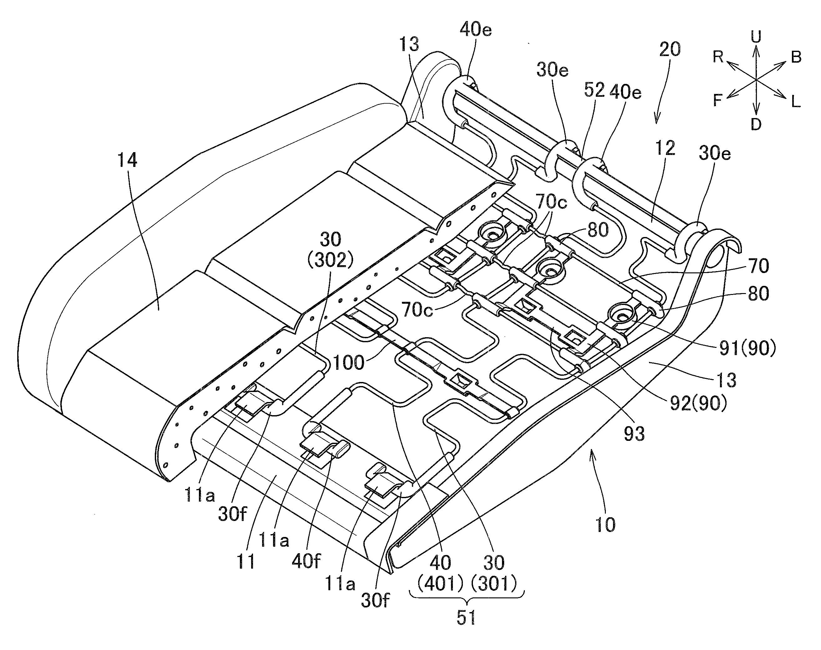
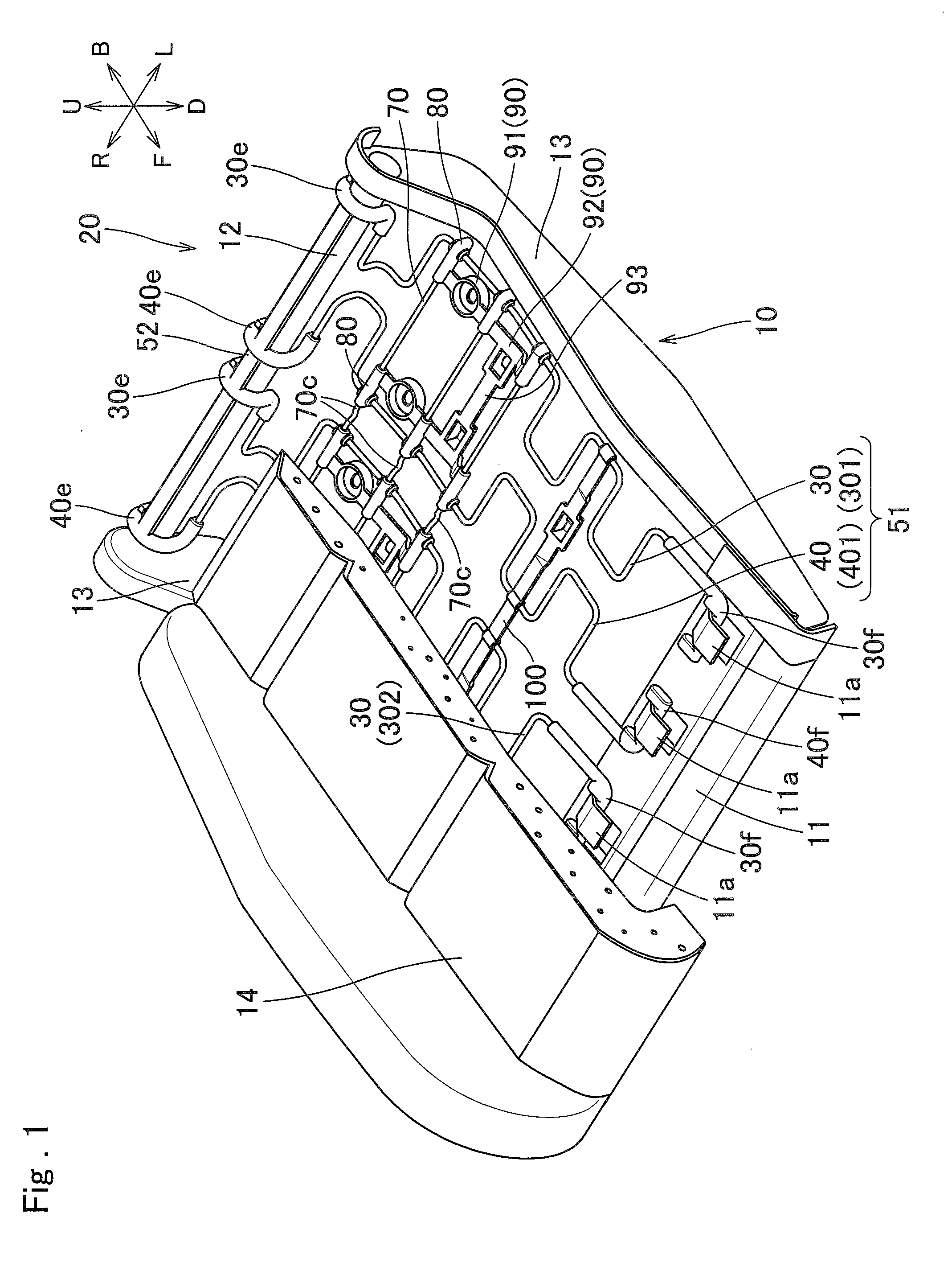
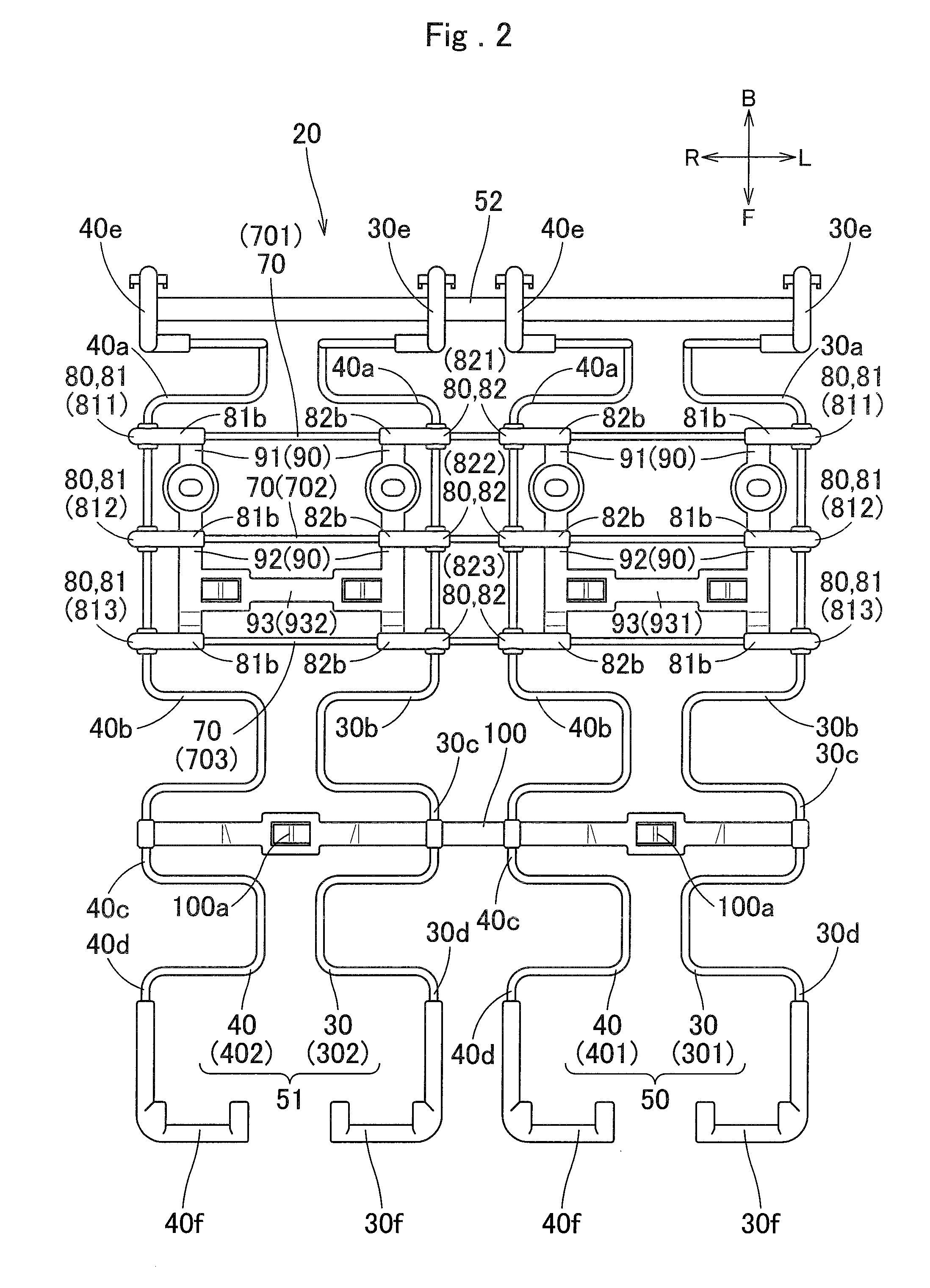
[0023]A first embodiment of a cushion body for a vehicle seat of the present invention will be described based on drawings. In the following description, the arrows in the respective drawings show directions in a state of being installed in a vehicle, and F means front, B means back, R means right, L means left, U means up, and D means down.

[0024]The cushion body 20 for a vehicle seat is, as shown in FIG. 1, attached in a manner stretching across between front and rear ends of a seat frame 10.

[0025]The seat frame 10 has a plate member 11 located at a front side, a tubular bar 12 located at a rear side, and side frames 13 and 13 that couple left-hand end portions of the plate member 11 and the bar 12 to each other and right-hand end portions of the same to each other, and is formed in a rectangular frame shape in a plan view. With a cushion pad 14 attached on an upper side of the seat frame 10, the cushion body 20 for a vehicle seat is arranged on a lower surface of the cushion pad 1...


PUM


Abstract

A cushion body for a vehicle seat is configured including spring members each having a plurality of bent portions, a stretching-across member disposed in a manner stretching across between the spring members, and a coupling member coupling the stretching-across member and the spring member. The stretching-across member is stretched across between the spring members in a manner arranged at a position different from that of a bent portion of the spring member, and the coupling member is formed in a manner not including the bent portion of the spring member.

Description

BACKGROUND OF THE INVENTION[0001]1. Field of the Invention[0002]The present invention relates to a cushion body for a vehicle seat to be attached to a seat frame so as to receive a load of an occupant.[0003]2. Description of the Related Art[0004]A conventional cushion spring (cushion body for a vehicle seat) disclosed in JP2009-172025 A has been provided. According thereto, the cushion spring is to be attached to a seat plate frame of a vehicle seat, and includes a wire spring formed by folding a straight spring wire rod into substantially U-shapes and a coupling member installed additionally to the wire spring and fixed by clips.[0005]Moreover, the coupling member is arranged in a manner connecting a tip corner portion and base corner portion of the wire spring(s), tip corner portions to each other, and / or base corner portions to each other.[0006]However, in the above-described cushion body for a vehicle seat, there has been a tendency that, because of the arrangement in a manner c...

Claims


Application Information

Patent Timeline
Patent Type & Authority Applications(United States)
IPC IPC(8): B60N2/70B60N2/64
CPCB60N2/646B60N2/7094B60N2/72
Inventor HOSOE, MASAYUKI
Owner SINDAI KARIYA AICHI JP
Learn More