Cylinder lock device

a technology of cylinder lock and lock rod, which is applied in the direction of cylinder lock, tumbler lock, lock application, etc., can solve the problem of difficulty in restoring the engagement lever to the temporary position, and achieve the effect of improving the mounting workability of the devi

Active Publication Date: 2015-12-03
KK TOKAI RIKA DENKI SEISAKUSHO +1
View PDF9 Cites 4 Cited by
  • Summary
  • Abstract
  • Description
  • Claims
  • Application Information

AI Technical Summary

Benefits of technology

[0027]According to one embodiment of the invention, a cylinder lock device can be provided that allows the engagement lever to be held into a predetermined direction during the mounting process so as to improve the mounting workability thereof.

Problems solved by technology

In such a configuration, although it is possible to hold the engagement lever at a temporary position without supporting by a hand, it is difficult to return the engagement lever back to the temporary position if, for example, an angle of the engagement lever with respect to the rotor is greatly changed during transportation, etc.

Method used


Image

  • Cylinder lock device
  • Cylinder lock device
  • Cylinder lock device

Examples


Embodiment Construction

[0035]An embodiment of the invention will be specifically described below in conjunction with the appended drawings.

[0036]Configuration of Cylinder Lock Device

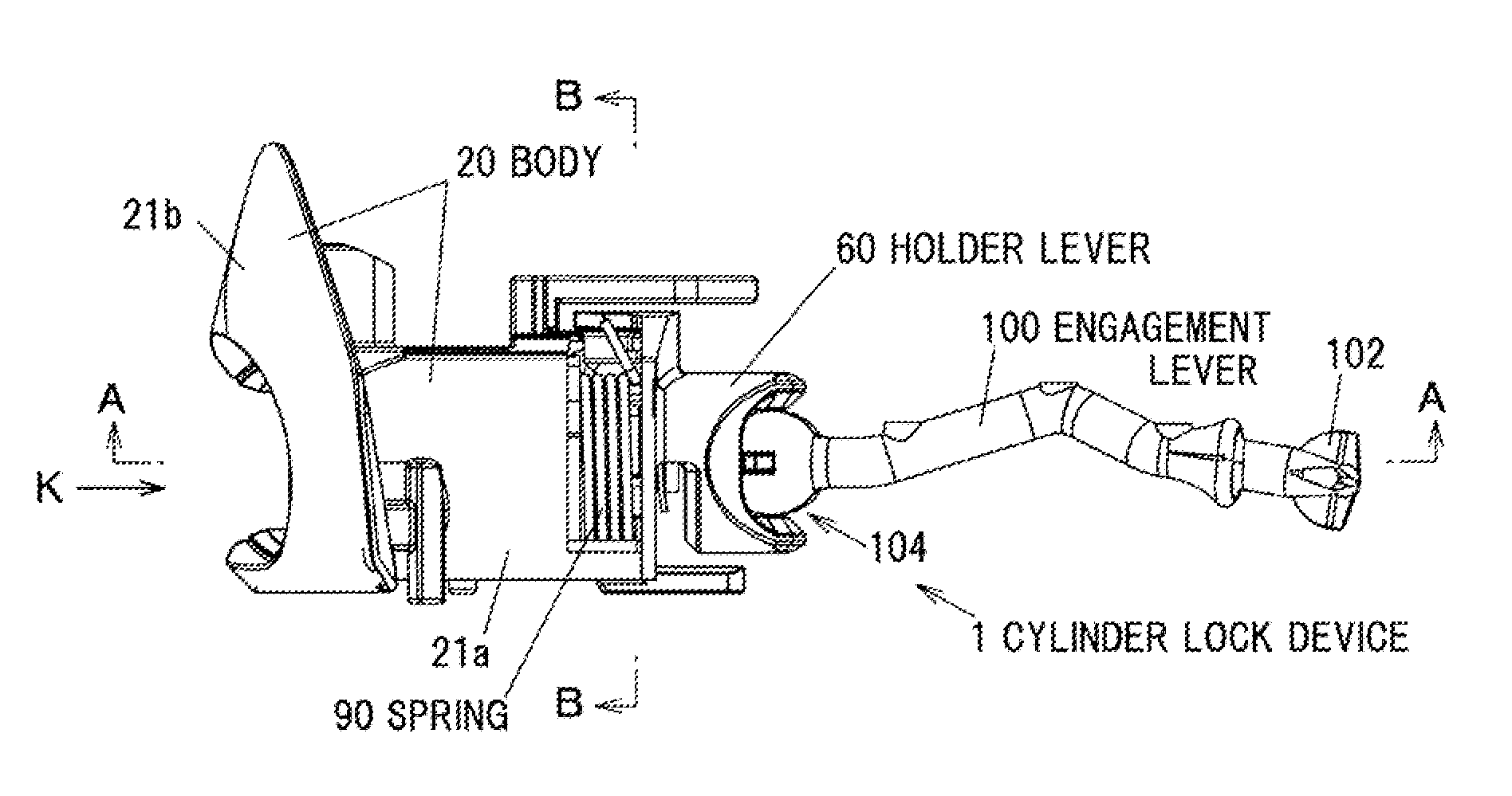
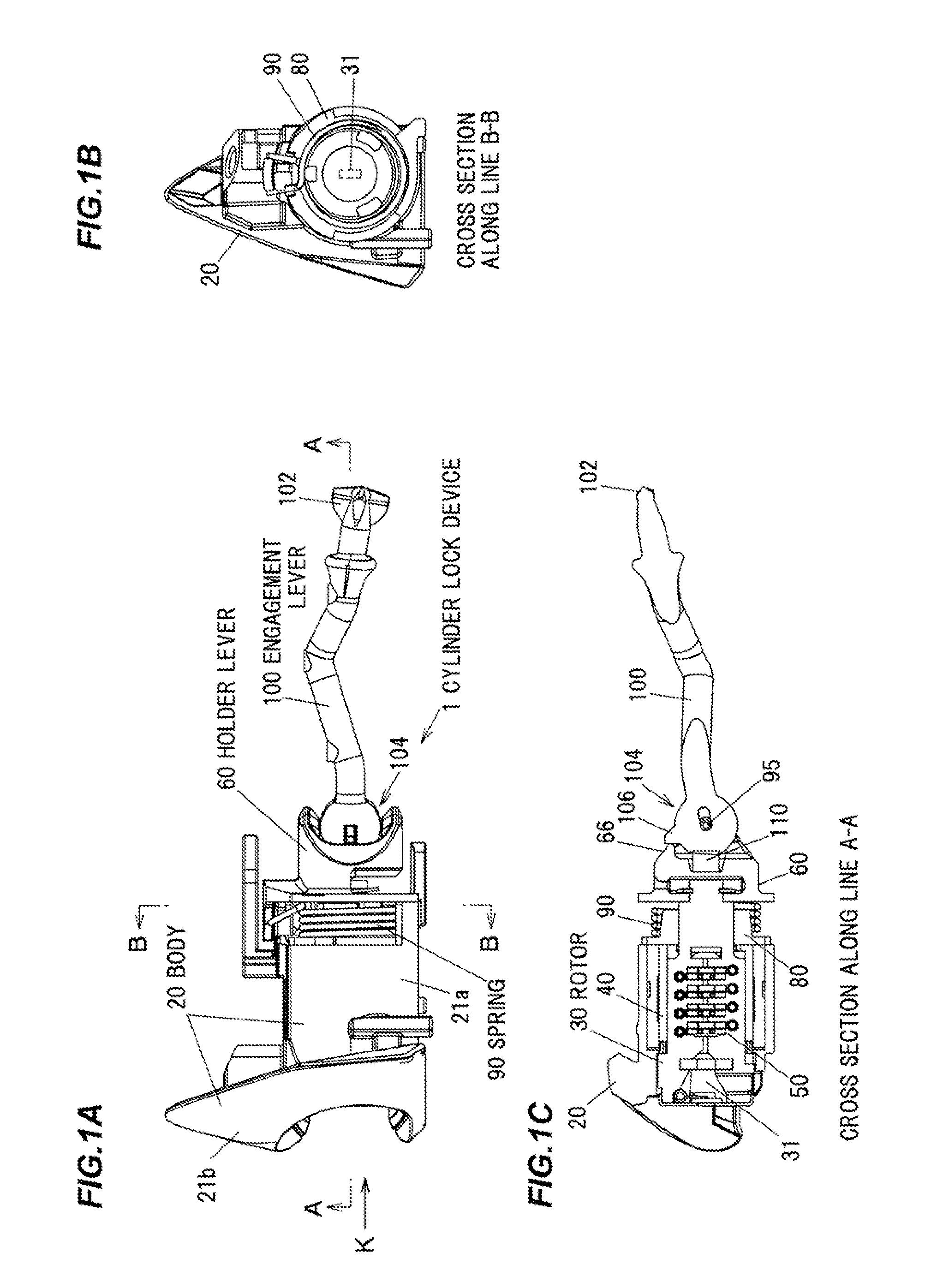
[0037]FIG. 1A is a side view showing a cylinder lock device in the embodiment of the invention, FIG. 1B is a cross sectional view taken on line B-B in FIG. 1A and FIG. 1C is a cross sectional view taken on line A-A in FIG. A.

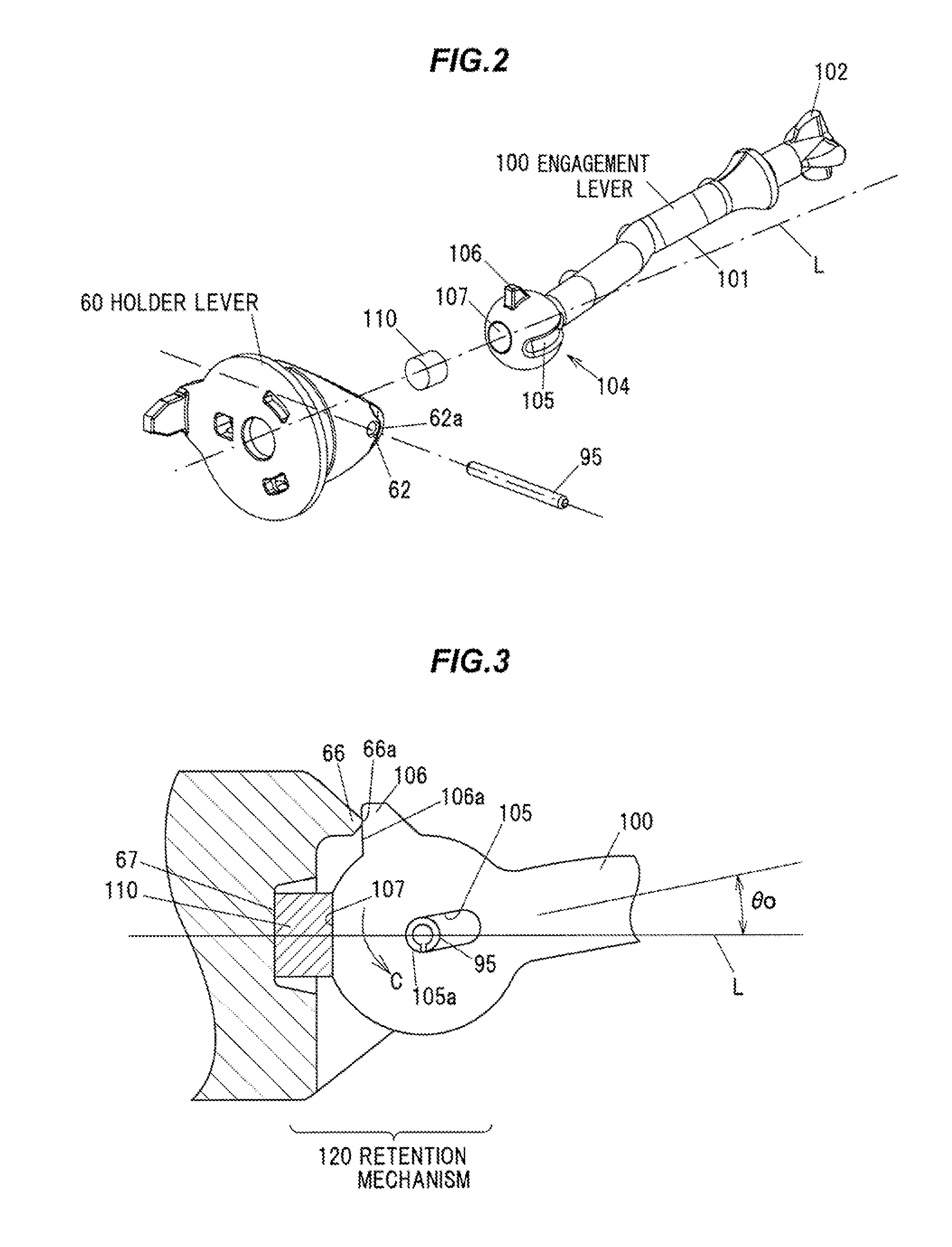
[0038]As shown in FIGS. 1A to 1C, a cylinder lock device 1 has a body 20, a rotor 30 rotatably arranged inside the body 20, a holder lever 60 rotationally driven along with rotation of the rotor 30, and an engagement lever 100 which is link-connected to the holder lever 60 so as to be angularly adjustable and rotationally driven along with the rotation of the rotor 30. In the cylinder lock device 1, a retention mechanism 120 to hold the engagement lever 100 into a predetermined direction relative to the body 20 is configured to force a protrusion 106 provided on the engagement lever 100 to contact the hold...


PUM


Abstract

A cylinder lock device includes a body, a rotor rotatably arranged inside the body, a holder lever rotationally driven according to a rotation of the rotor, an engagement lever that is link-connected to the holder lever so as to be angularly adjustable and rotationally driven according to a rotation of the rotor, and a retention mechanism to hold the engagement lever into a predetermined direction relative to the body. The retention mechanism is configured to force a protrusion on the engagement lever to contact the holder lever by an elastic force thereof.

Description

[0001]The present application is based on Japanese patent application No. 2014-114070 filed on Jun. 2, 2014, the entire contents of which are incorporated herein by reference.BACKGROUND OF THE INVENTION[0002]1. Field of the Invention[0003]The invention relates to a cylinder lock device for locking or unlocking door handle operation.[0004]2. Description of the Related Art[0005]In general, cylinder lock devices for vehicle door are installed around a handle. In a cylinder lock device, a rotor is provided to rotationally move in accordance with insertion and operation of a key and an engaging member is pivotally coupled to and rotates together with the rotor. The engaging member is connected to a lock mechanism arranged in a door panel and the lock mechanism is shifted to the locked or unlocked state by a turning force of the rotor (JP-A-2000-34851).[0006]In this cylinder lock device, a long hole is formed on an engagement lever so that the engagement lever is pivotally coupled to the ...

Claims


Application Information

Patent Timeline
Patent Type & Authority Applications(United States)
IPC IPC(8): E05B27/00
CPCY10T70/7486E05B27/0007E05B79/22E05B85/06E05B27/0046E05B79/20E05B79/12
Inventor KUSHIDA, TOMOHIDEISHIKAWA, YOSHIKI
Owner KK TOKAI RIKA DENKI SEISAKUSHO
Why Eureka
Try Eureka