

Wheel Motor Device
- Summary
- Abstract
- Description
- Claims
- Application Information
AI Technical Summary
Benefits of technology
Problems solved by technology
Method used
Image

Examples
first embodiment
[0054]One preferred embodiment of a wheel motor device according to the present invention will now be described with reference to the accompanied drawings.
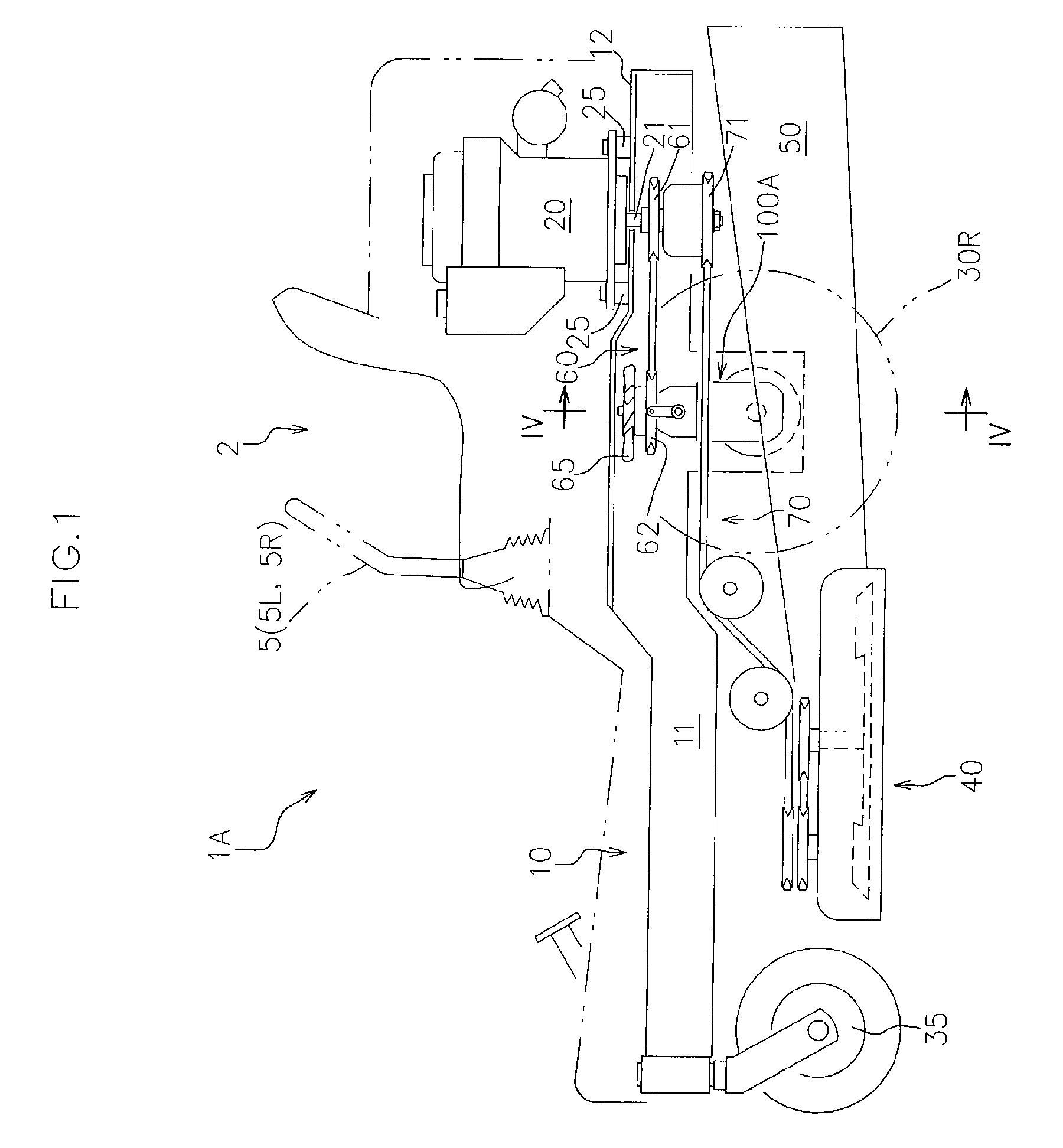
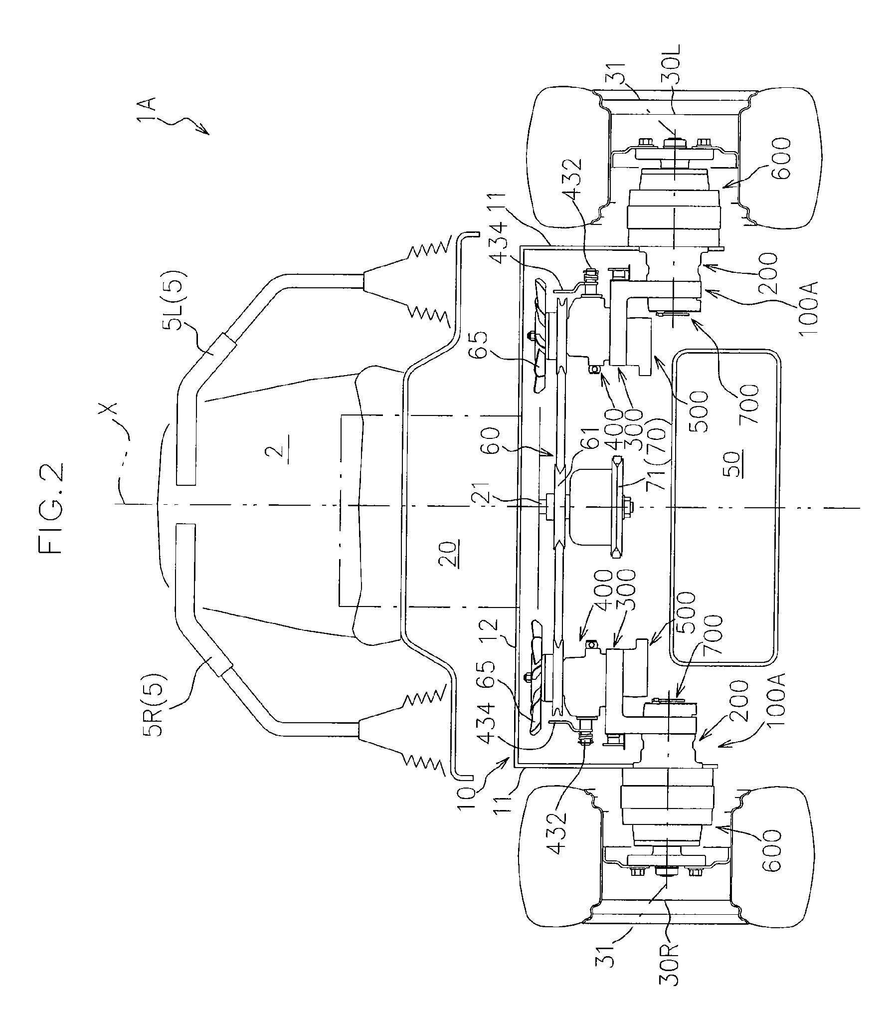
[0055]FIGS. 1 to 3 respectively shows a side view, a plan view and a hydraulic circuit diagram of a working vehicle IA to which a wheel motor device 100A according to the present embodiment is applied.
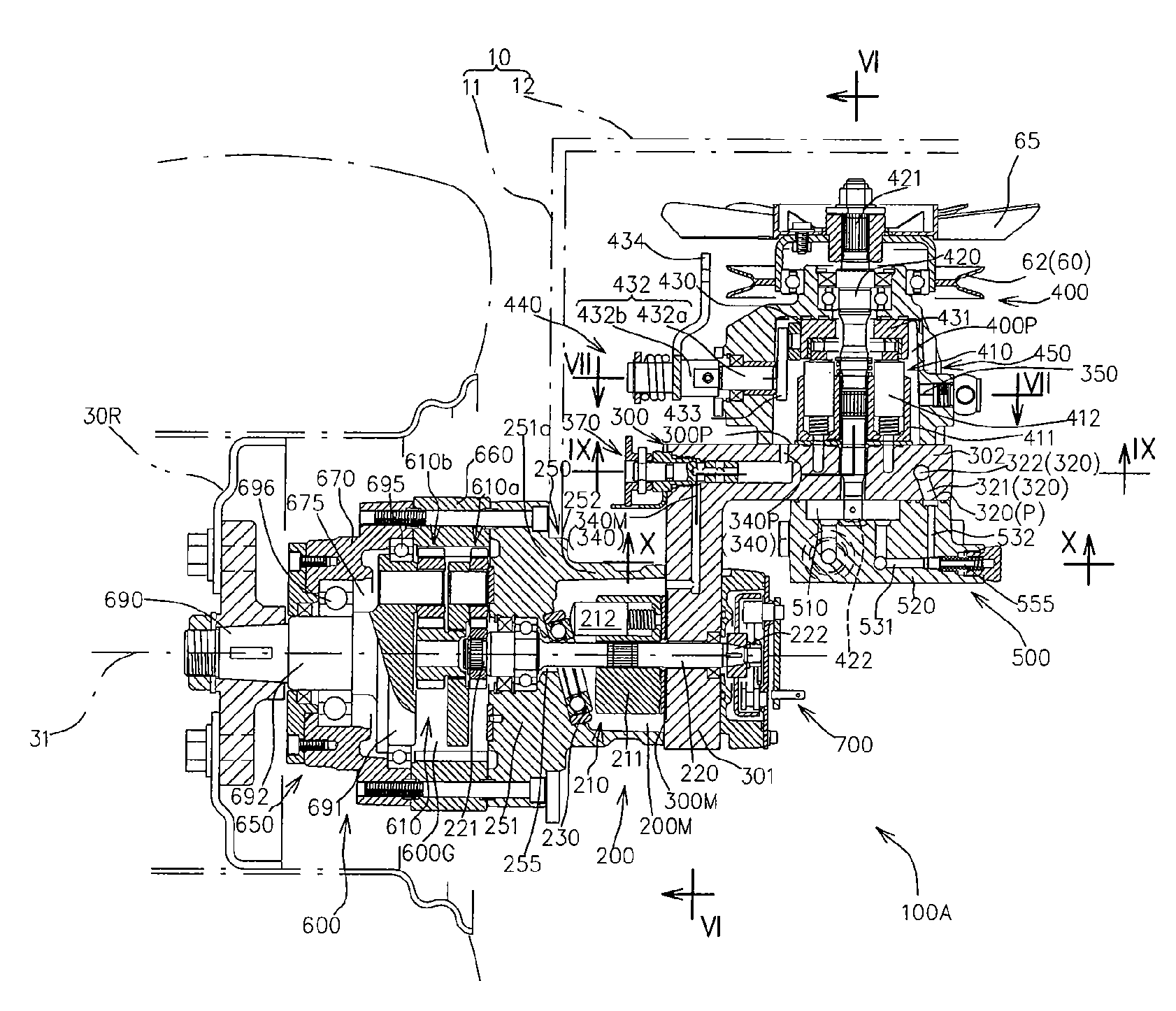
[0056]The wheel motor device 100A according to the present embodiment includes a hydraulic motor unit 200 that has a hydraulic motor main body 210 forming an HST in cooperation with a hydraulic pump main body 410 and operatively driving a corresponding driving wheel 30 (see FIG. 3), and is capable of being arranged close to the corresponding driving wheel 30 (see FIG. 1).
[0057]The working vehicle will be firstly explained.
[0058]The working vehicle 1A includes, as shown in FIGS. 1 to 3, a vehicle frame 10 having a pair of main frames 11 that extends along a longitudinal direction of the vehicle and a cross member 12 that extends betwe...
second embodiment
[0214]Another embodiment of the wheel motor device according to the present invention will now be described with reference to the accompanying drawings.
[0215]FIG. 11 shows a hydraulic circuit diagram of a working vehicle 1B to which a wheel motor device 100B according to the present embodiment is applied.
[0216]FIG. 12 shows a vertical cross sectional front view of the wheel motor device 100B according to the present embodiment with applied to the right-side driving wheel 30R.
[0217]In the drawings, the same elements as those of the first embodiment have been given the same reference characters to omit a detailed description thereof.
[0218]The wheel motor device 100B according to the present embodiment is mainly different from the wheel motor device 100A according to the first embodiment in that the motor space 200M and the pump space 400P are independent from each other, and a self-suction structure for self-suctioning the operational fluid for the HST is provided.
[0219]Specifically, ...
third embodiment
[0250]Still another embodiment of the wheel motor device according to the present invention will now be described with reference to the accompanying drawings.
[0251]FIGS. 16 and 17 respectively show a side view and a front view of a working vehicle 1C to which a wheel motor device 100C according to the present embodiment is applied.
[0252]FIG. 18 shows a vertical cross sectional front view of the wheel motor device 100C according to the present embodiment with applied to the right-side driving wheel 30R.
[0253]In the drawings, the same elements as those of the first and second embodiments have been given the same reference characters to omit a detailed description thereof.
[0254]In the wheel motor devices 100A, 100B according to the first and second embodiments, the horizontal portion 302 of the port block 300, 300B supporting the hydraulic pump main body 420 and the pump case 450 extends inward in the width direction of the vehicle from the upper end of the vertical portion 301 (see FI...
PUM
 Abstract
Description
Claims
Application Information