Fixture, fixing assembly, and fixation method for fixing power line to base member

Active Publication Date: 2017-04-13
TOYOTA JIDOSHA KK
View PDF4 Cites 2 Cited by
  • Summary
  • Abstract
  • Description
  • Claims
  • Application Information

AI Technical Summary

Benefits of technology

The present invention provides a fixture, fixing assembly, and fixation method that can prevent the holding jig from getting bigger and can fix the power lines to the base member as needed. This means that the fixture can be mounted on the holding jig, allowing for easy attachment to the base member and power lines.

Problems solved by technology

If the holding jig receives a vibration or the like and swings around or moves, a stress is applied to a fastening part (a caulking portion) between the power line and the power-line-side terminal or a fastening part (a welded portion) between the power line and the stator coil, which may deteriorate these fastening parts.
This causes an increase in cost of the holding jig.
Further, in a case where the holding jig is upsized or increased in weight, a load to the power line at the time of an assembling operation of the power line increases, which deteriorates assembly workability of the power line.
Further, a large swing that causes deterioration of the fastening parts does not occur in all vehicles and rotary electric machines, so it is wasteful to provide the fastening portion in all holding jigs.

Method used


Image

  • Fixture, fixing assembly, and fixation method for fixing power line to base member
  • Fixture, fixing assembly, and fixation method for fixing power line to base member
  • Fixture, fixing assembly, and fixation method for fixing power line to base member

Examples


Embodiment Construction

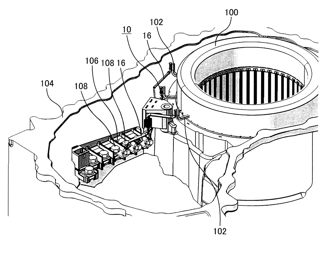
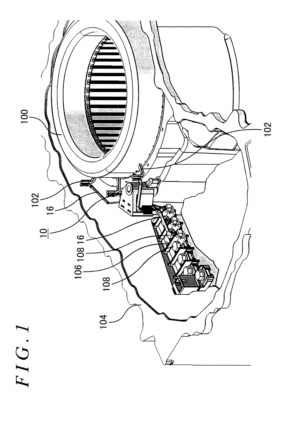
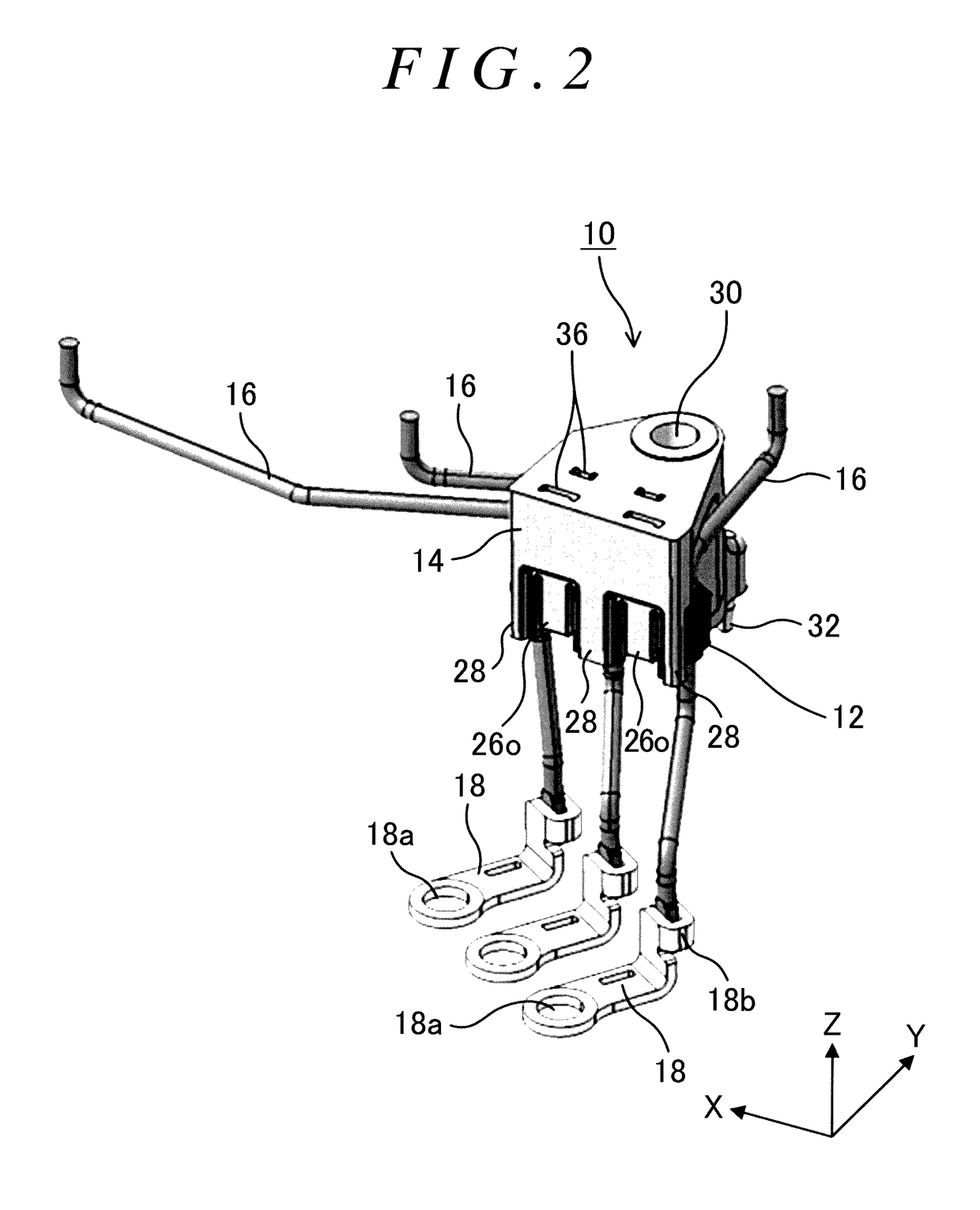
[0033]Exemplary embodiments will be described below with reference to drawings. FIG. 1 is a view illustrating a state where power lines 16 are fixed by use of a fixing assembly 10 according to an exemplary embodiment. Further, FIG. 2 is a perspective view of the fixing assembly 10, and FIG. 3 is a perspective view of a holding jig 12. Further, FIG. 4 is a side view of a fixture 14, FIG. 5 is a front view of the fixture 14, FIG. 6 is a sectional view of the fixing assembly 10 taken along a line A-A in FIG. 5, and FIG. 7 is a sectional view taken along a line B-B in FIG. 6. Further, in the following description, in order to facilitate the description, a longitudinal direction of the holding jig 12 is referred to as an “X-direction,” a short direction thereof is referred to as a “Y-direction,” and a direction perpendicular to the X-direction and the Y-direction is referred to as a “Z-direction.”

[0034]The fixing assembly 10 of the present embodiment fixes, to a motor case 104 as a base ...


PUM


Abstract

A fixture for fixing, to a motor case, a holding jig configured to hold a plurality of power lines connected to respective stator coils so as to restrict a relative movement between the plurality of power lines includes: a fastening hole through which a bolt for fastening the fixture to a motor case is inserted; and a mounting portion on which the holding jig holding the power lines is mountable. The mounting portion includes: an accommodation space in which to accommodate the holding jig; and holding pawls for sandwiching the holding jig.

Description

CROSS-REFERENCE TO RELATED APPLICATIONS[0001]This application claims priority from Japanese Patent Application No. 2015-199270 filed on Oct. 7, 2015, the disclosure of which, including the specification, drawings and abstract, is incorporated herein by reference in its entirety.BACKGROUND[0002]1. Technical Field[0003]The present disclosure relates to a fixture, a fixing assembly, and a fixation method each for fixing, to a base member, a power line connected to a rotary electric machine.[0004]2. Description of Related Art[0005]Conventionally, there has been known an in-vehicle rotary electric machine provided in an electrically driven vehicle such as a hybrid vehicle or an electric vehicle. A power line for supplying an electric power from a power source is connected to such a rotary electric machine. Generally, one end of the power line is connected to a stator coil, and the other end of the power line is connected to a terminal block attached to a motor case. Further, in most case...

Claims


Application Information

Patent Timeline
IPC IPC(8): H02K5/22H02K3/50
CPCH02K3/50H02K5/225H02K2203/06H02G3/32H02K15/0062
Inventor KURONO, YOUSUKEMAKIDO, YASUHIRO
Owner TOYOTA JIDOSHA KK
Why Eureka
Try Eureka