
Model-Based Optimal Control For Stall Margin Limit Protection in an Aircraft Engine

a technology for aircraft engines and optimal control, applied in the field of gas turbine engines, can solve problems such as unstable flow in the compressor, compressor stall is a limiting factor in the operation, and the compressor section of the engine may experience compressor stall,

Active Publication Date: 2015-12-03
RTX CORP
View PDF11 Cites 13 Cited by
  • Summary
  • Abstract
  • Description
  • Claims
  • Application Information

AI Technical Summary

Benefits of technology

The patent describes a control system for a gas turbine engine that uses a hybrid model predictive control (HMPC) module. This module receives power goals and operability limits, and determines a multi-variable control command for the engine based on these inputs, sensor signals, and an estimated stall margin remaining. The control system also includes a goal generation module and an actuator for controlling the engine. The technical effect of this patent is to provide a more efficient and effective control system for gas turbine engines, allowing for better performance and operability under various operating conditions.

Problems solved by technology

Over the course of an operating cycle of a gas turbine engine, a compressor section of the engine may experience compressor stall.
Compressor stall is a limiting factor in the operation of gas turbine engines.
In modern gas turbine engines, unstable flow may develop in the compressor during acceleration phases and / or under high altitude and lower speed flight conditions.
Such unstable flow may lead to stall, which may increase turbine temperature and mechanical vibration along with simultaneously reducing the cooling air supplied to the turbine.
Stall may lead to turbine failure if the compressor stall is not recognized and corrective action is not taken.
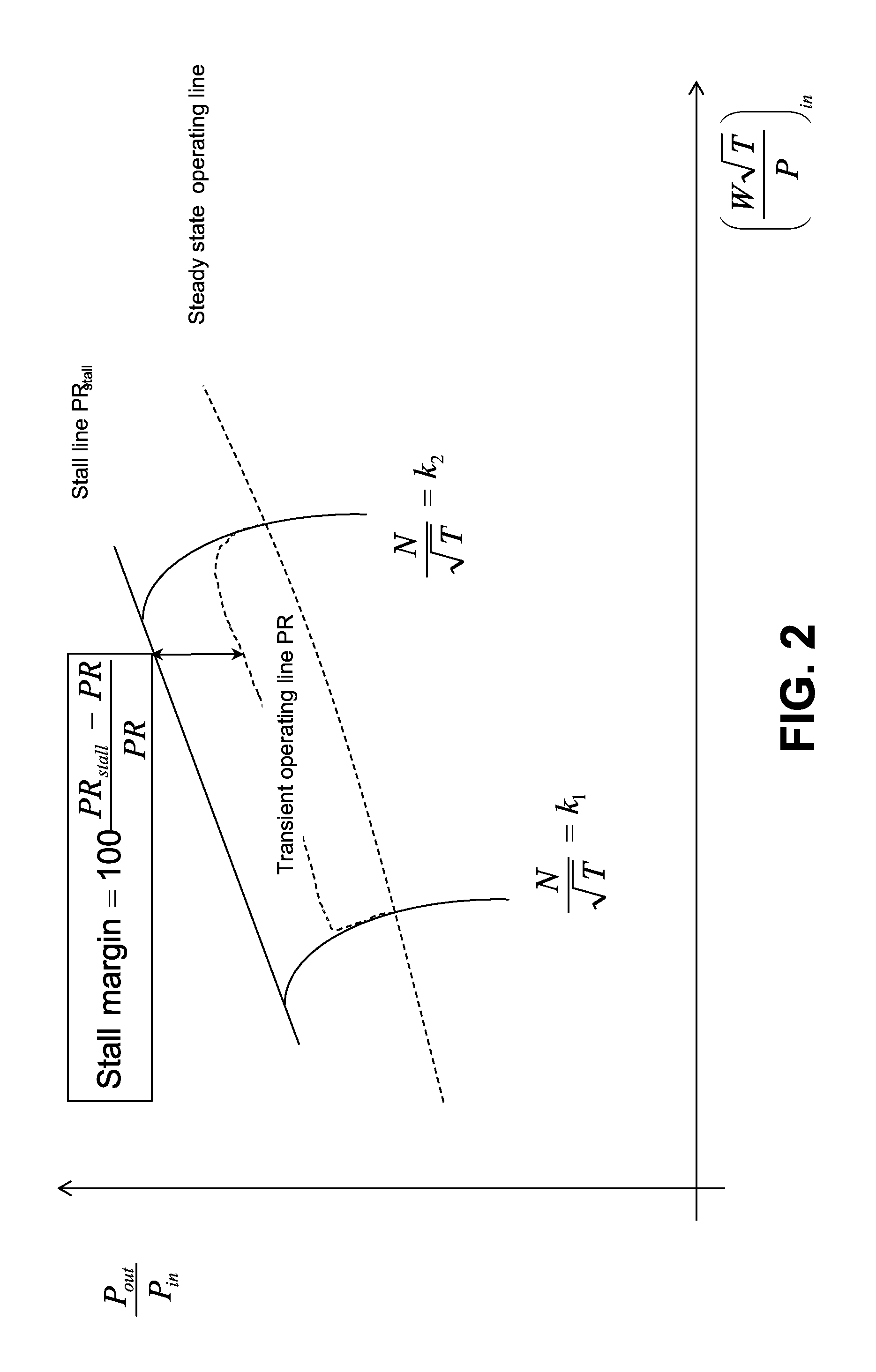
In addition, other transient effects such as heat transfer, tip clearance, and variable geometry and bleed control may result in large variations in the overall compressor operating line.
Such variations may in turn, affect individual compressor stage operating conditions and a margin to aerodynamic instability.

Method used


Image

  • Model-Based Optimal Control For Stall Margin Limit Protection in an Aircraft Engine
  • Model-Based Optimal Control For Stall Margin Limit Protection in an Aircraft Engine
  • Model-Based Optimal Control For Stall Margin Limit Protection in an Aircraft Engine

Examples


Embodiment Construction

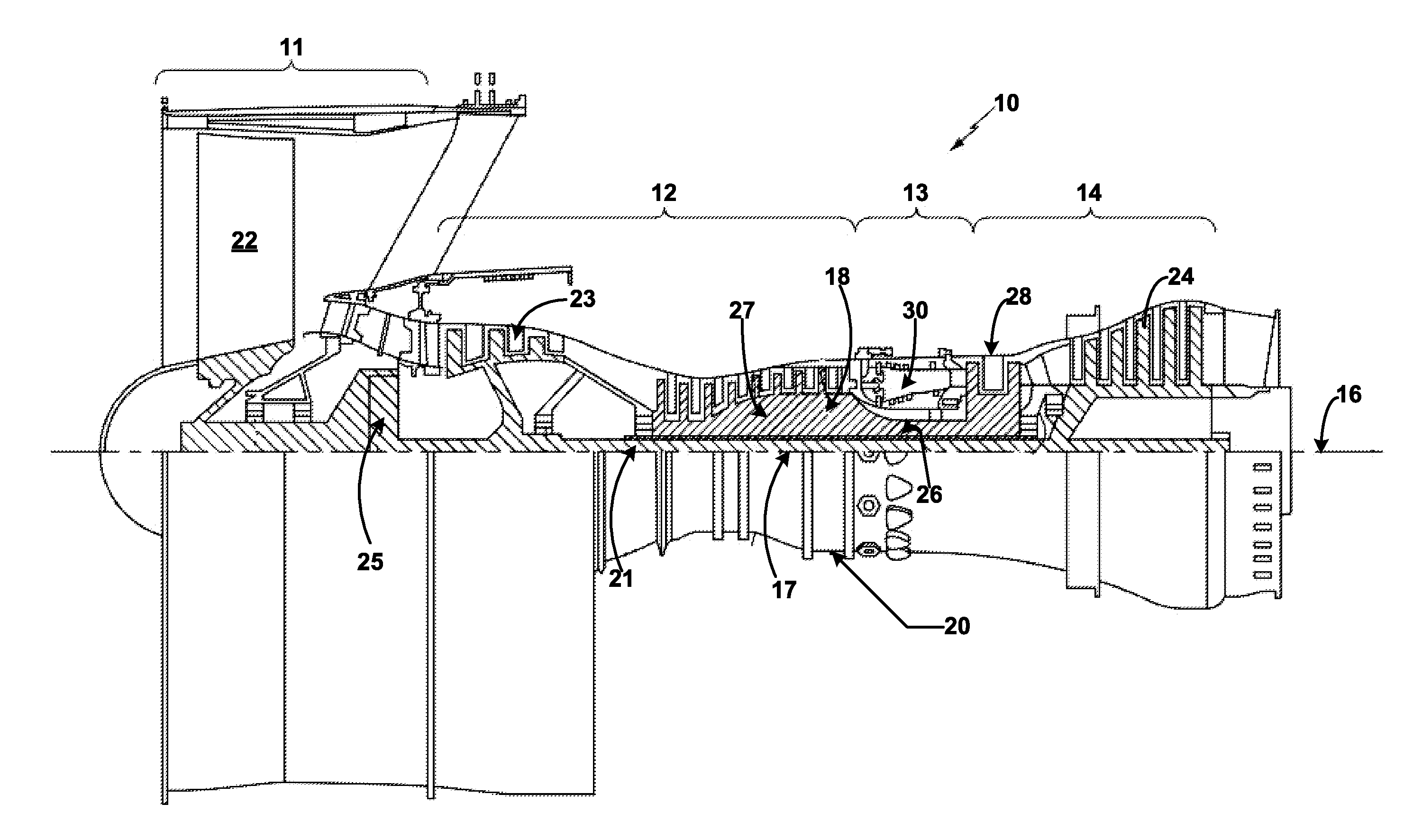
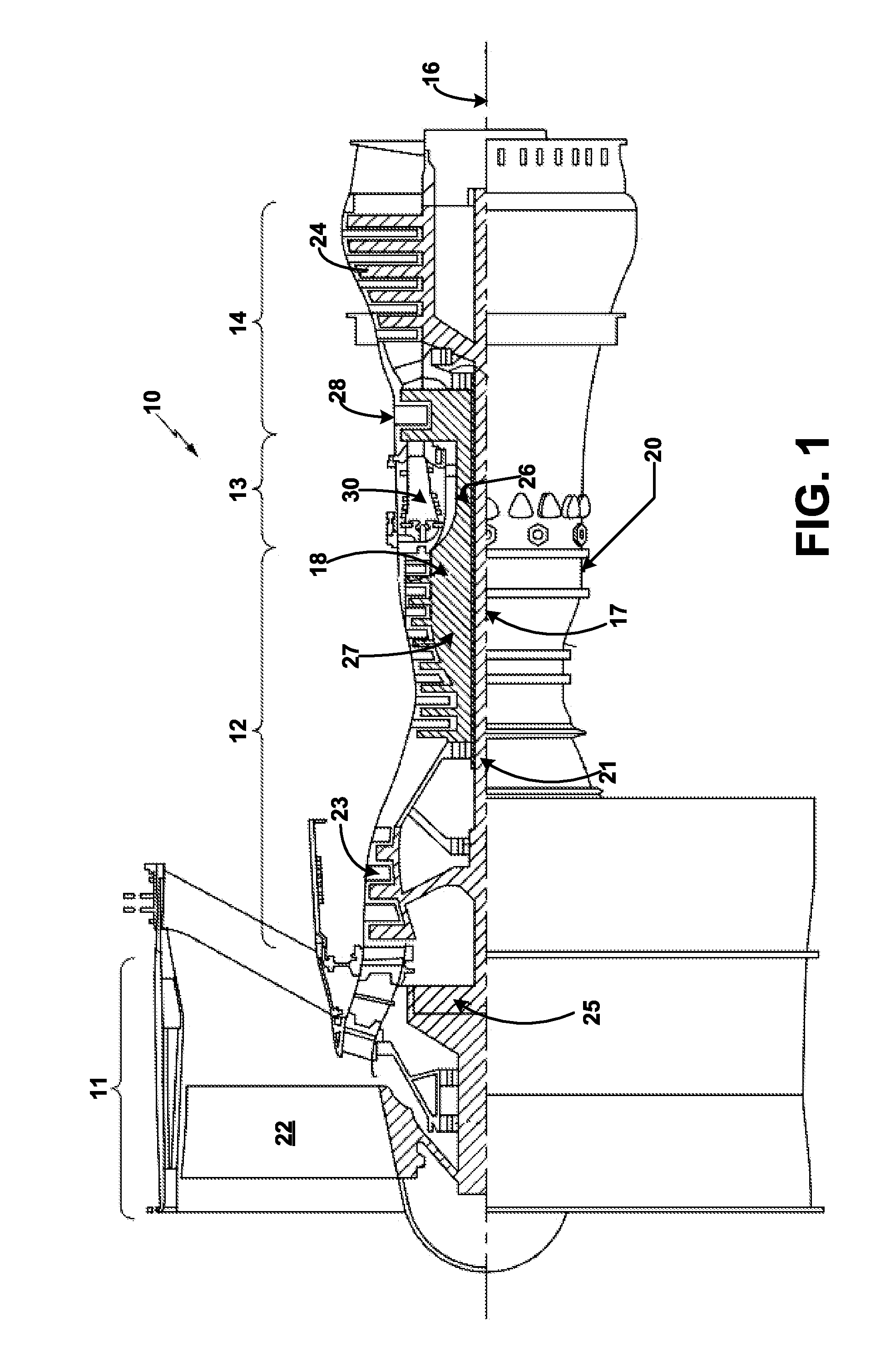
[0033]Referring to the drawings, and with specific reference to FIG. 1, a gas turbine engine constructed in accordance with the present disclosure is generally referred to by reference numeral 10. Such a gas turbine engine 10 can be used for any number of different applications including, but not limited to, generation of aircraft thrust, rotorcraft power and land-based power. Moreover, it is to be understood that the sectional view provided in FIG. 1 is included simply to provide a basic understanding of the various sections in a gas turbine engine, and not to limit the invention thereto. The present disclosure extends to all types of gas turbine engines used in all types of applications.

[0034]The gas turbine engine 10 may have a fan section 11, the fan section 11 drawing in ambient air and directing the ambient air to a compressor section 12. The incoming air is greatly compressed by the compressor section 12 and directed to a combustor section 13 where it is mixed with fuel and c...


PUM


Abstract

A control system for a gas turbine engine, a method for controlling a gas turbine engine, and a gas turbine engine are disclosed. The control system may include a hybrid model predictive control (HMPC) module, the HMPC module receiving power goals and operability limits and determining a multi-variable control command for the gas turbine engine, the multi-variable control command determined using the power goals, the operability limits, actuator goals, sensor signals, and synthesis signals. The control system may further include system sensors for determining the sensor signals and a non-linear engine model for estimating corrected speed signals and synthesis signals using the sensor signals, the synthesis signals including an estimated stall margin remaining. The control system may further include a goal generation module for determining actuator goals for the HMPC module using the corrected speed signals and an actuator for controlling the gas turbine engine based on the multivariable control command.

Description

CROSS-REFERENCE TO RELATED APPLICATION[0001]This application is a non-provisional patent application claiming priority under 35 USC §119(e) to U.S. Provisional Patent Application Ser. No. 62 / 006,653 filed on Jun. 2, 2014.TECHNICAL FIELD OF THE DISCLOSURE[0002]The present disclosure relates to gas turbine engines, and more particularly, to control systems for gas turbine engines.BACKGROUND OF THE DISCLOSURE[0003]Over the course of an operating cycle of a gas turbine engine, a compressor section of the engine may experience compressor stall. Compressor stall is a limiting factor in the operation of gas turbine engines. In modern gas turbine engines, unstable flow may develop in the compressor during acceleration phases and / or under high altitude and lower speed flight conditions. Such unstable flow may lead to stall, which may increase turbine temperature and mechanical vibration along with simultaneously reducing the cooling air supplied to the turbine. Stall may lead to turbine fail...

Claims


Application Information

Patent Timeline
Patent Type & Authority Applications(United States)
IPC IPC(8): F02C9/00F01D17/00G16Z99/00
CPCF02C9/00F01D17/00F05D2260/83F05D2260/81F05D2260/80F05D2270/44F05D2270/334F02C9/52F02C9/54F05D2270/304F05D2270/303F05D2270/301F04D27/0261G16Z99/00Y02B30/70B60T7/12
Inventor CAI, CHAOHONGADAMS, JOSHUAMEISNER, RICHARD P.
Owner RTX CORP
Learn More