
Recoil mitigation and buttstock floating system, method, and apparatus

a technology of rmbf and rmbf adapter, which is applied in the direction of butts, weapons, weapon components, etc., can solve the problems of inaccurate shots, firearms are not in a proper shoulder position, and the angle of firearms must be held at non-orthogonal and non-ideal angles

Active Publication Date: 2015-12-03
IRVIN ROBERT +1
View PDF2 Cites 18 Cited by
  • Summary
  • Abstract
  • Description
  • Claims
  • Application Information

AI Technical Summary

Benefits of technology

The present disclosure is directed to a buffer tube for firearms that can change its buttstock angle, as well as a recoil mitigation and buttstock floating (RMBF) device for firearms. The technical effects of the patent text include improved recoil mitigation, reduced buttstock angle, and improved buttstock grip. The RMBF device can be used with firearms that have a fixed buttstock or a movable buttstock. The method of manufacturing the buffer tube involves attaching a bracket for mounting a buttstock to a tube component that connects to a firearm, and a helical spring disposed inside the tube component. The RMBF device can be used with firearms that have a fixed firearm portion and a movable buttstock. The bracket can be locked at different positions to change the angle of the buttstock. The RMBF device can also include an expansive component that applies expansive force to push the bracket away from the tube until a bolt catches to create a maximum extension of the device. The technical effects of the patent text include improved recoil mitigation, reduced buttstock angle, and improved buttstock grip.

Problems solved by technology

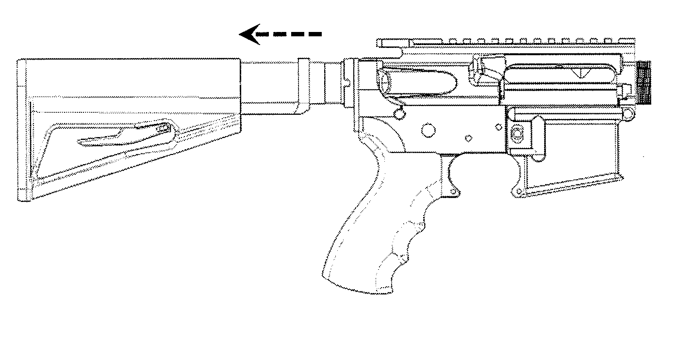
However, when a firearm user is under cover, the firearm must often be held at non-orthogonal and non-ideal angles.
As a result, the firearm is not in a proper shoulder location.
When the buttstock of the firearm is not positioned in the proper shoulder location, shots are inaccurate due to lack of firearm stability.
Further, significant recoil drift exists, thus making several shots in quick succession impractical.
Finally, recoil may possibly injure the user.
Each of which are undesirable.
In order to use such different scopes, the firearm should be tilted to allow the operator to line up the scope with the line of sight and take aim at a target, however, this will position the firearm buttstock in a non-ideal position for the operator to take a precision shot or control the firearm recoil.
As expected, such an approach is impractical for field use and inconvenient, at best, for enthusiast use.
However, according to the Nelson design, it would be more difficult to quickly and easily switch between positions as Nelson uses locking dowel pins to secure the buttstock in a desired position.

Method used


Image

  • Recoil mitigation and buttstock floating system, method, and apparatus
  • Recoil mitigation and buttstock floating system, method, and apparatus
  • Recoil mitigation and buttstock floating system, method, and apparatus

Examples


example 1

[0241]Turning to FIGS. 19a through 19e, a first example RMBF adapter mechanism 1900 may comprise a first housing 1902 (e.g., an upper housing), a second housing 1904 (e.g., a lower housing), a helical spring 1912 disposed therebetween, and a screw 1910 (or bolt, or the like) configured to secure the first housing 1902 to the second housing 1904. As illustrated, the first housing 1902 and the second housing 1904 may be generally shaped like cups, that is, a circular planar surface having a cylindrical wall (or portion thereof) at the circumference of the circular planar surface.

[0242]When assembled, the open side of the first housing 1902 faces the open end of the second housing 1904. One of the housings, the first housing 1902 is illustrated, may be sized such that the outside diameter of the cylindrical wall is about equal to, or slightly less than, the inside diameter of the other housing's cylindrical wall (e.g., the second housing 1904). This configuration enables the housings t...

example 2

[0249]FIGS. 20a through 20e illustrate a second example RMBF adapter mechanism 2000, which may comprise a first housing 1902, a second housing 1904, a helical spring 1912 disposed therebetween, and a screw 1910 configured to secure the first housing 1902 to the second housing 1904. Rather than providing an angle guide selector 1914 cutout from the second housing 1904 (i.e., a housing with a larger outside diameter) as illustrated with regard to FIGS. 19a through 19e, the angle guide selector 1914 cutout may be placed on the housing with the smaller outside diameter (e.g., the second housing 1904). As illustrated, this arrangement would require additional cuts on the base of the housing with the larger outside diameter to allow the telescopic relative motion between housings to take place; the guide pin 1916 in this arrangement may be supported in two places which facilitates a better support to the guide pin 1916.

example 3

[0250]FIGS. 21a through 21e illustrate a third example RMBF adapter mechanism 2100, which may comprise a first housing 1902, a second housing 1904, a helical spring 1912 disposed therebetween, and a screw 1910 configured to secure the first housing 1902 to the second housing 1904. Rather than providing a guide pin 1916, a notch 2102 may be formed on the second housing 1904 that is configured to engage one of a plurality of angle selection grooves 310 positioned on the first housing 1902. FIGS. 22a through 22c illustrate a rear perspective view of the third RMBF adapter mechanism 2100 in a default upright position, a default upright position, and a second axially rotated position, respectively.


PUM


Abstract

A buffer tube for firearms, including assault rifles, carbines, shotguns, and other rifles is disclosed. The floating buffer tube comprises a recoil mitigation mechanism, including a helical spring or an elastic or viscous energy absorption device, and a buttstock mounting bracket mounted outside the buffer tube. The buttstock mounting bracket can rotate relative to the buffer tube, which changes the axial angle of the buttstock relative to the firearm. The angle can be locked under an expansive force by forcing a bolt or pin into grooves to select the proper axial angle of the buttstock relative to the firearm in the field without the user having to disarm himself to perform the angle change.

Description

CROSS REFERENCE TO RELATED APPLICATIONS[0001]This application claims priority to U.S. Provisional Patent Application No. 61 / 955,452, filed on Mar. 19, 2014 and entitled “AR Floating Buffer Tube,” and U.S. Provisional Patent Application No. 62 / 117,335, filed on Feb. 17, 2015 and entitled “Recoil Mitigation And Buttstock Floating System, Method, And Apparatus,” each by Robert Irvin, each of which are hereby incorporated by reference in its entirety.FIELD OF THE INVENTION[0002]The invention relates to recoil mitigation and buttstock floating (RMBF) devices and RMBF adapter mechanisms for firearms, such as carbines, shotguns, assault rifles, and rifles as a whole.BACKGROUND OF THE INVENTION[0003]A buffer tube, such as those for a collapsible buttstock on a rifle (such as the M4), is typically a hollow tube that is closed (or partially closed) at one end, wherein the open end is attached to a receiver coupled to a firearm. A buffer tube serves two general functions: first, it holds the r...

Claims


Application Information

Patent Timeline
Patent Type & Authority Applications(United States)
IPC IPC(8): F41A3/78F41C23/14
CPCF41C23/14F41A3/78F41C23/06F41C23/20
Inventor IRVIN, ROBERT
Owner IRVIN ROBERT
Learn More