Light amount adjustment device, optical device, and image capturing apparatus
a technology of light amount adjustment and adjustment device, which is applied in the direction of camera diaphragm, shutter, optics, etc., can solve the problems of difficult to form the light passage aperture into the desired aperture shape, poor image quality, and difficulty in maintaining the movement posture of the respective aperture blades
- Summary
- Abstract
- Description
- Claims
- Application Information
AI Technical Summary
Benefits of technology
Problems solved by technology
Method used
Image

Examples
first embodiment
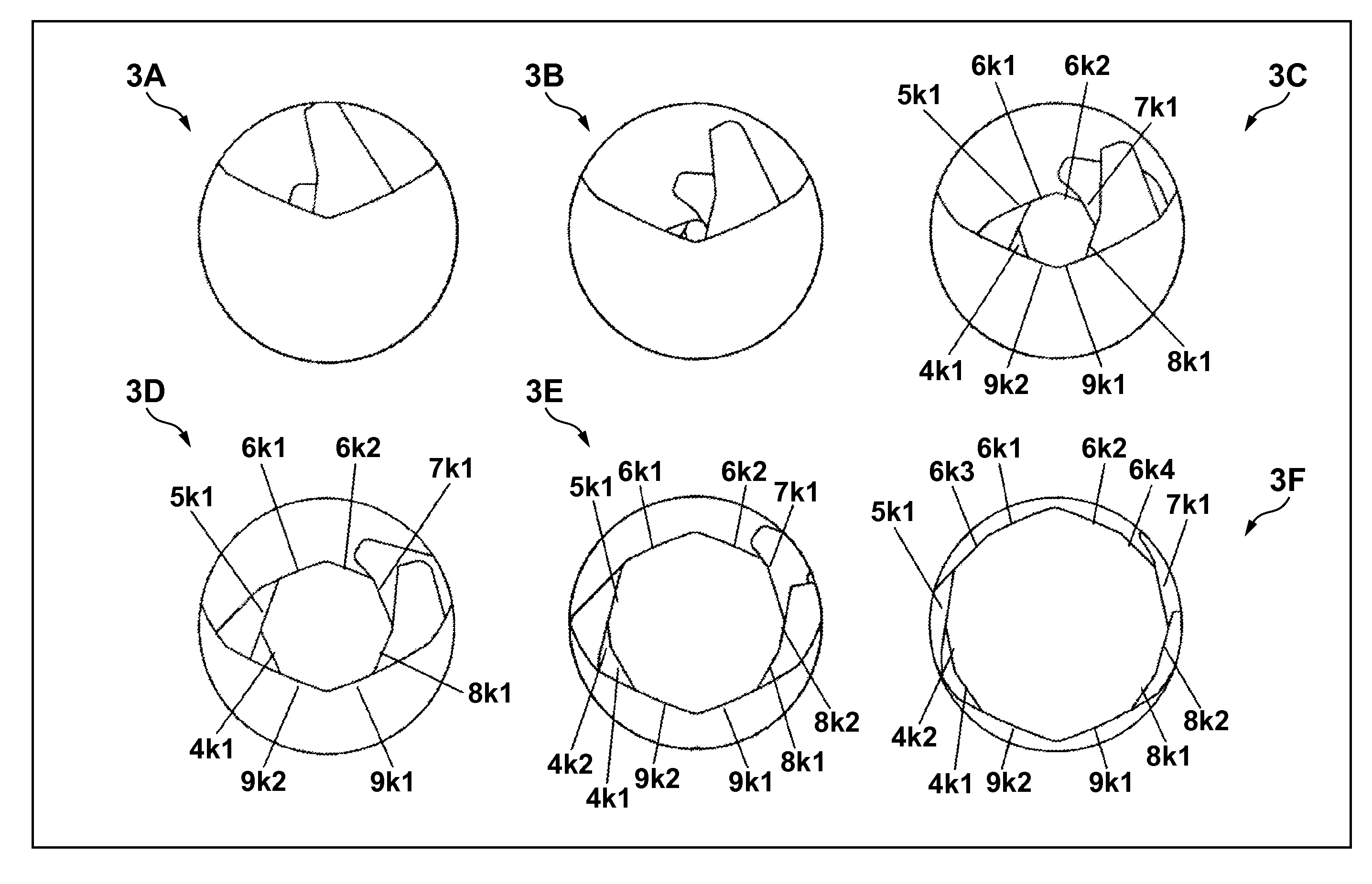
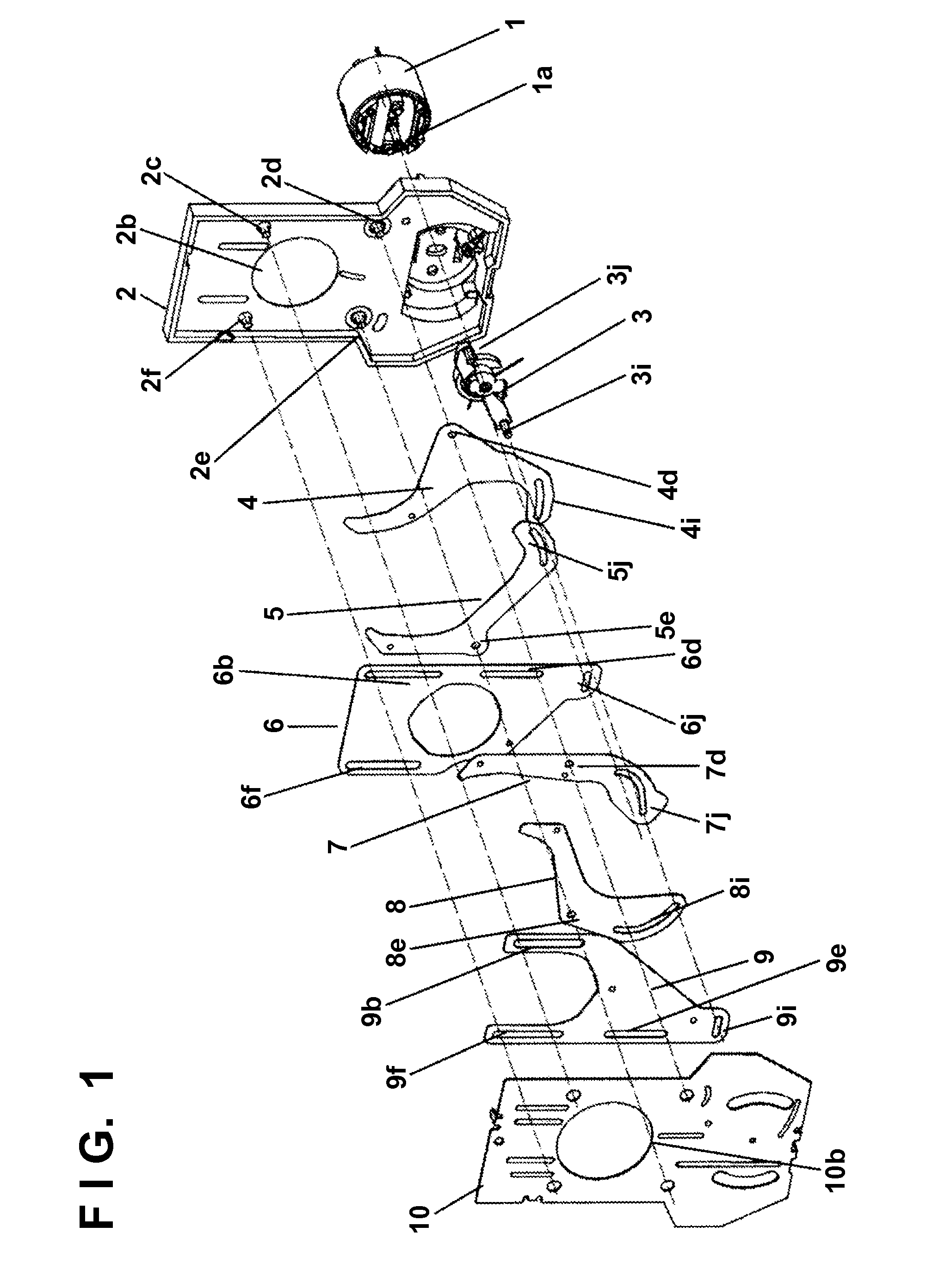
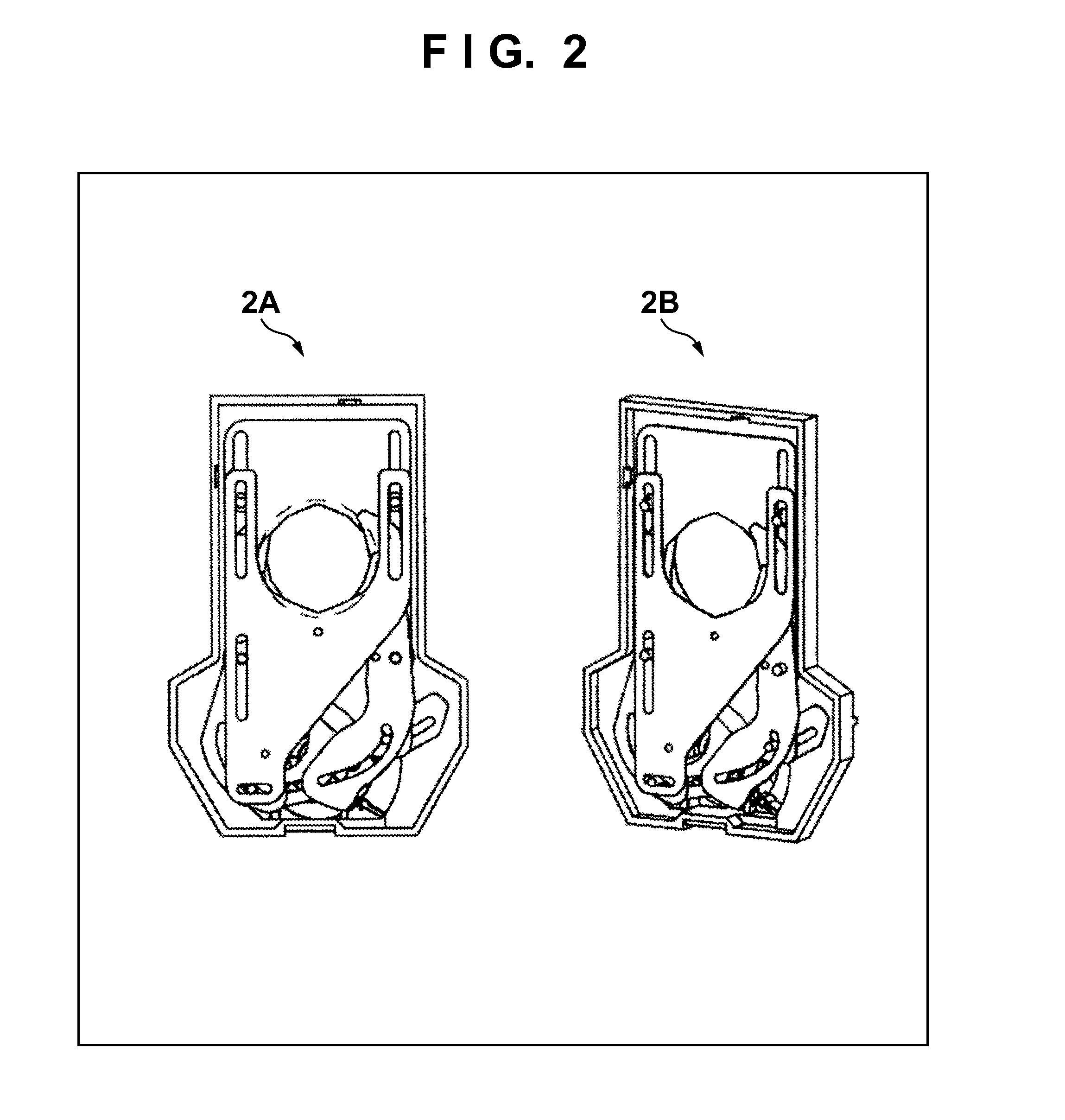
[0027]FIG. 1 is an exploded view showing a diaphragm device serving as a light amount adjustment device according to the first embodiment of the present invention. Also, 2A in FIG. 2 and FIGS. 6 to 8 show the diaphragm device when viewed from a direction (optical axis direction) in which light passes through a diaphragm aperture formed by aperture blades 4 to 9 serving as light amount adjustment blades. Note that FIG. 2 shows a state in which a cover plate 10 shown in FIG. 1 is removed. Further, 2B in FIG. 2 shows the diaphragm device shown in 2A of FIG. 2 when viewed obliquely. In these drawings, the longitudinal direction, which is the top-and-bottom direction, of the diaphragm device is equivalent to a “direction in which the aperture blade moves linearly in a direction crossing a light passage direction”, and will be called an optical axis cross direction in the following description. The right-and-left direction of the diaphragm device in these drawings will be called a widthwi...
second embodiment
[0070]FIG. 9 is an exploded view showing a diaphragm device according to the second embodiment of the present invention. The diaphragm device according to the second embodiment is implemented by providing, in the diaphragm device shown in FIG. 1, an ND filter 12 that can move back and forth and attenuates the amount of light passing through the diaphragm aperture. In FIG. 9, the same reference numerals as those in FIG. 1 denote the same parts as those shown in FIG. 1, and a description thereof will not be repeated.
[0071]An ND holding plate 13 holds the ND filter 12. The ND holding plate 13 is arranged on a side opposite to aperture blades 4 to 9 with respect to a cover plate 10. An outer cover plate 14 forms, between the outer cover plate 14 and the cover plate 10, a space where the ND holding plate 13 is moved. The outer cover plate 14 is attached to a base plate 2.
[0072]A sub-base plate 16 on which an ND driving unit 17 is fixed is attached to the outer cover plate 14. The ND driv...
third embodiment
[0076]An example of a housing structure in the diaphragm device according to one of the first and second embodiments will be described. In the third embodiment, projecting portions 2r and 10r and the like (to be described later) are added to the structure according to the first embodiment. The same reference numerals as those in FIG. 1 denote the same parts as those described in the first or second embodiment, and a description thereof will not be repeated.
[0077]As shown in 10A and 10B of FIG. 10, a case member 10 constituting part of a housing in the diaphragm device is engaged with shafts 2c, 2d, 2e, and 2f on one surface side of a base plate 2 to form, between the case member 10 and the base plate 2, a blade accommodation space (blade chamber 100) that accommodates aperture blades 4 to 9. The case member 10 has a fixed opening 10b corresponding to a fixed opening 2b formed in the base plate 2. More specifically, in a state in which the case member 10 is engaged with the base plat...
PUM
 Abstract
Description
Claims
Application Information
 - Generate Ideas
- Intellectual Property
- Life Sciences
- Materials
- Tech Scout
- Unparalleled Data Quality
- Higher Quality Content
- 60% Fewer Hallucinations
Browse by: Latest US Patents, China's latest patents, Technical Efficacy Thesaurus, Application Domain, Technology Topic, Popular Technical Reports.
© 2025 PatSnap. All rights reserved.Legal|Privacy policy|Modern Slavery Act Transparency Statement|Sitemap|About US| Contact US: help@patsnap.com