Lighting device and display device

a technology of illumination device and display device, which is applied in the direction of lighting and heating apparatus, planar/plate-like light guides, instruments, etc., can solve the problem of uneven luminance and achieve the effect of suppressing uneven luminan

Inactive Publication Date: 2015-10-22
SHARP KK
View PDF1 Cites 35 Cited by
  • Summary
  • Abstract
  • Description
  • Claims
  • Application Information

AI Technical Summary

Benefits of technology

[0023]According to the present invention, it is possible to provide an illumination device that suppresses uneven luminance, and a display device provided with this illumination device.

Problems solved by technology

As stated in Patent Document 1, in an edge-lit backlight device, when the light entering inside the light guide plate is reflected by the light guide plate side face that is on the opposite side to the light-receiving face (opposite surface hereinafter), this reflected light is known to be the cause of uneven luminance.

Method used


Image

  • Lighting device and display device
  • Lighting device and display device
  • Lighting device and display device

Examples


embodiment 1

[0039]Embodiment 1 of the present invention will be described while referring to FIGS. 1 to 7. The present embodiment illustrates an example of a liquid crystal display device (display device) provided with a backlight device (illumination device). Mutually intersecting X, Y and Z axes are shown in each drawing. FIG. 5 is the criteria for the vertical direction. The upper side of this drawing is the front side, and the lower side of this drawing is the back side.

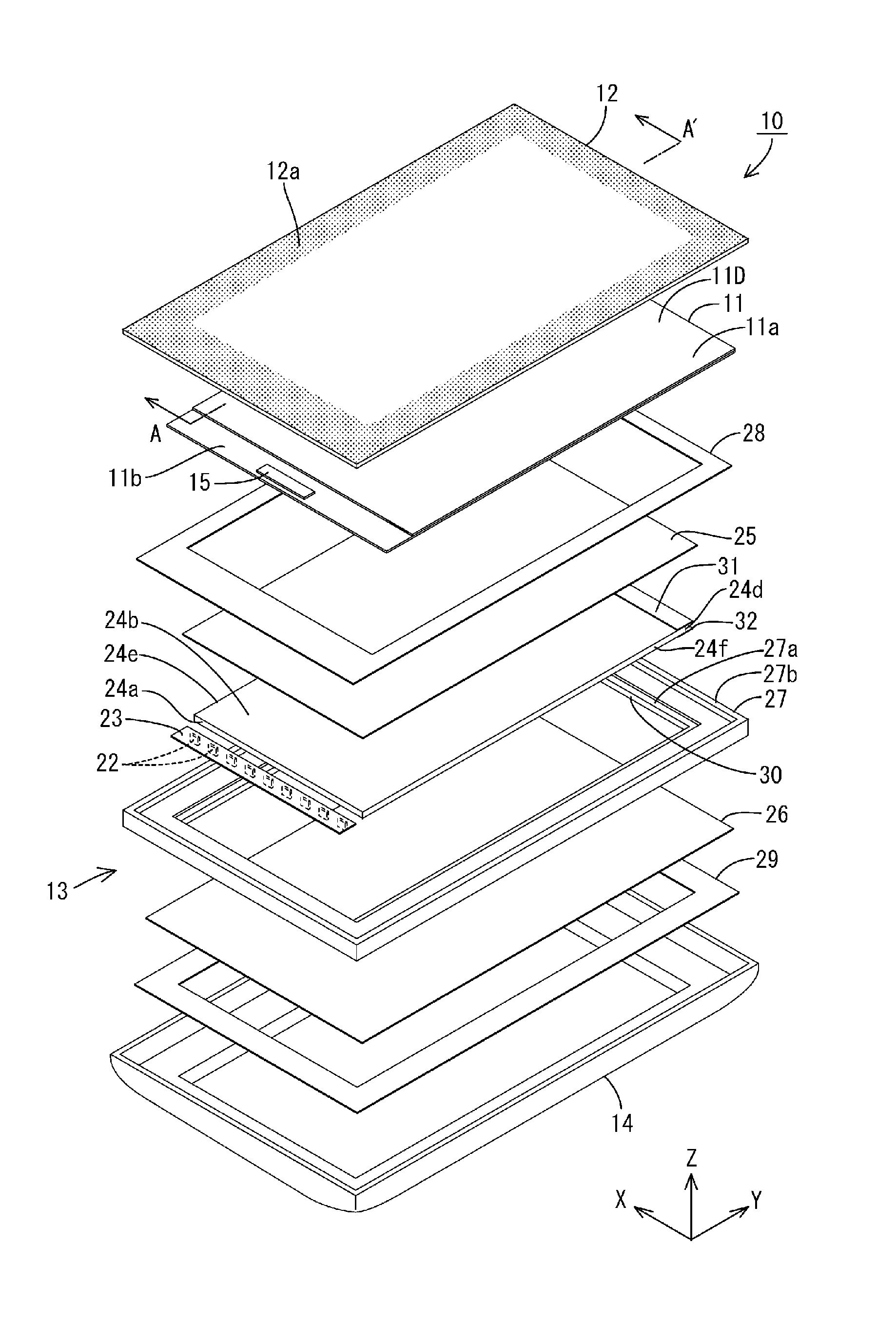
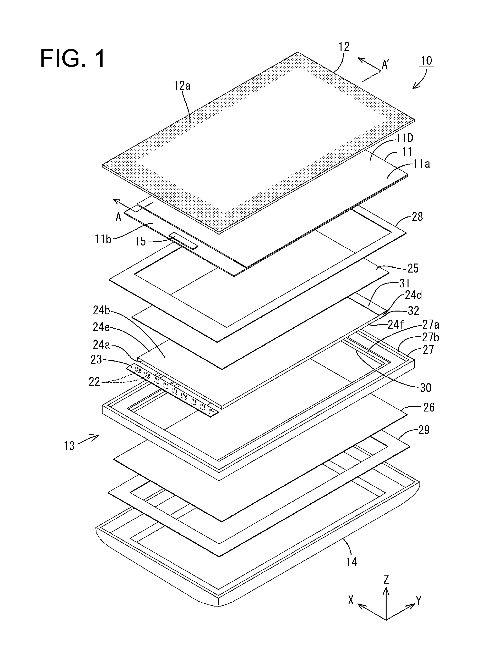
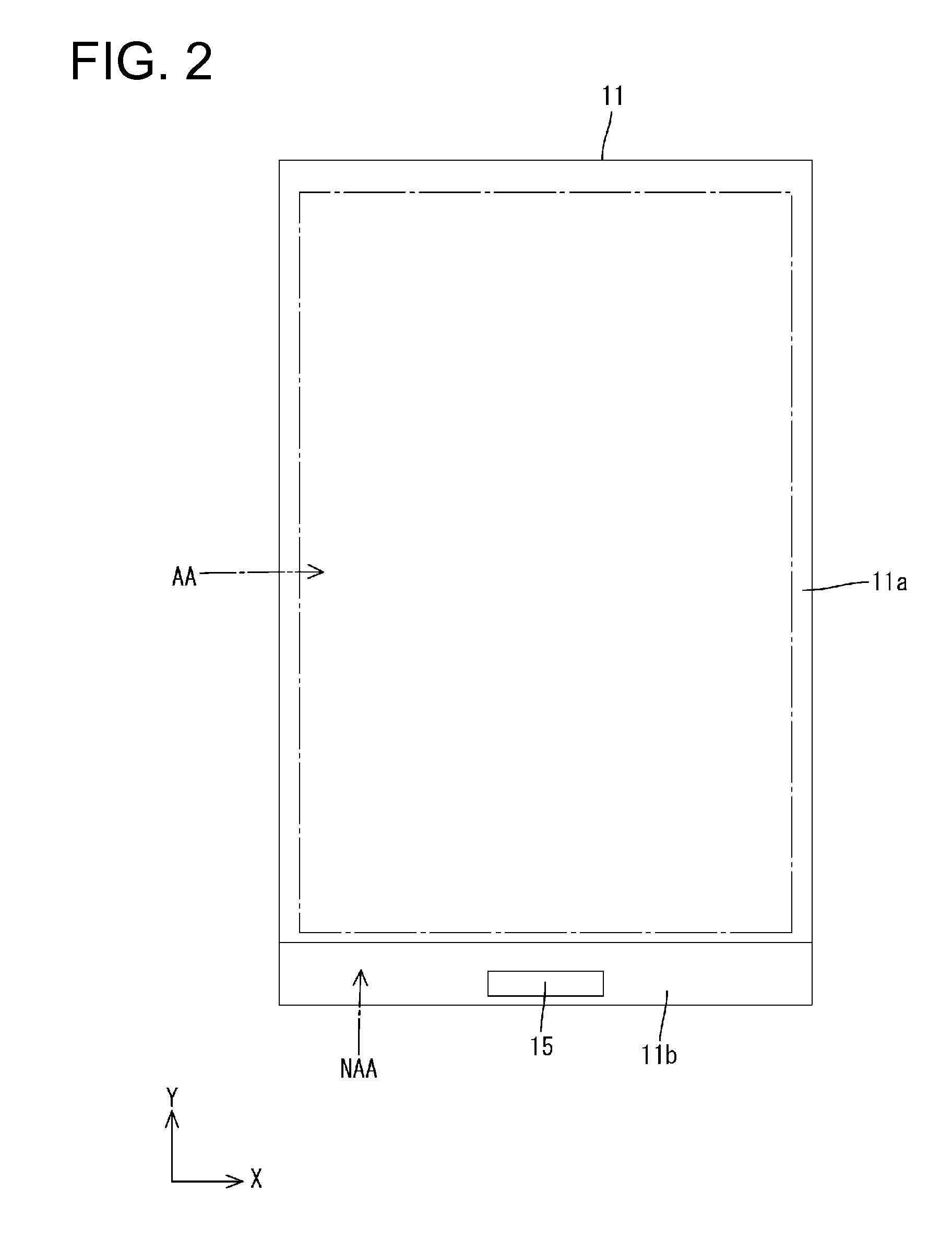
[0040]FIG. 1 is an exploded perspective view of a liquid crystal display device 10 according to Embodiment 1. As shown in FIG. 1, the overall the liquid crystal display device 10 forms a longitudinal rectangular shape. The liquid crystal display device 10 is provided with: a liquid crystal panel (display panel) 11 in which a front surface is a display surface 11D for displaying an image, and a rear surface is an opposite surface 11O; a cover panel 12 disposed so as to face the display surface 11D of the liquid crystal panel ...

embodiment 2

[0076]Next, Embodiment 2 of the present invention will be described while referring to FIG. 8. FIG. 8 is a partial cross-sectional view of a liquid crystal display device 10A according to Embodiment 2. In the embodiments that follow, the same reference characters as Embodiment 1 are given to parts that are the same as Embodiment 1, and detailed descriptions (configurations, effect, and so forth) will be omitted. The present embodiment illustrates a liquid crystal display device 10A provided with a backlight device 13A. The basic configuration of the liquid crystal display device 10A of the present embodiment is the same as that of Embodiment 1. However, a second light absorbing member 32A of the liquid crystal display device 10A of the present embodiment differs from that of Embodiment 1. Specifically, the second light absorbing member 32A of the present embodiment is formed from a light absorbing coated film that is formed on a light reflective sheet 26.

[0077]The second light absor...

embodiment 3

[0079]Embodiment 3 of the present invention will be described next while referring to FIG. 9. FIG. 9 is a partial cross-sectional view of a liquid crystal display device 10B according to Embodiment 3. The present embodiment illustrates a liquid crystal display device 10B provided with a backlight device 13B. The basic configuration of the liquid crystal display device 10B of the present embodiment is the same as that of Embodiment 1. However, a second light absorbing member 32B of the liquid crystal display device 10B of the present embodiment differs from that of Embodiment 1. Specifically, the second light absorbing member 32B of the present embodiment is formed directly on a rear periphery 24c1 on a rear surface 24c of a light guide plate 24.

[0080]The second light absorbing member 32B is formed from a black-colored coated film (coating material) that absorbs light. The black-colored coated film is prepared by mixing a black coloring agent into a base resin, for example. Furthermo...


PUM


Abstract

An illumination device of the present invention is provided with: a light source; a light guide plate having a light-receiving face that faces the light source and on which light that has been generated from the light source is incident, an opposite surface that is on the opposite side to the light-receiving face, and a light-exiting surface from which light that has entered the light guide plate from the light-receiving face exits; a first wall disposed along the front-back direction of the light guide plate and having a light absorbing surface that faces the opposite surface and absorbs light that has leaked out from the light guide plate; and a first light absorbing member that extends between a front periphery adjacent to the opposite surface on the light-exiting surface and a front end of the first wall, and absorbs light that has leaked out from the light guide plate.

Description

TECHNICAL FIELD[0001]The present invention relates to an illumination device and a display device.BACKGROUND ART[0002]In recent years, liquid crystal panels have come into widespread use as display panels for displaying images on the display devices of electronic equipment such as portable information terminals (smartphones and tablet-type personal computers, for example). In addition to the liquid crystal panels, backlight devices (illumination devices) for supplying light to the liquid crystal panels are also being mounted in these types of display devices.[0003]As stated in Patent Document 1, for example, an edge-lit (or a side-lit) that has been provided with a light guide plate formed from a transparent plate-shaped member, and a light source (an LED, for example) that is disposed so as to face the side face of this light guide plate, is known as the aforementioned backlight device. Light generated from the light source of the backlight device enters inside the light guide plat...

Claims


Application Information

Patent Timeline
Patent Type & Authority Applications(United States)
IPC IPC(8): F21V8/00
CPCG02B6/0088G02B6/0055G02B6/005
Inventor ARAKI, RYOHYAGI, SHUGOHATTA, KAZUYA
Owner SHARP KK
Why Eureka
Try Eureka