Illuminating apparatus, illuminating method and display apparatus

A technology for lighting equipment and lighting direction, which is applied to lighting and heating equipment, mechanical equipment, lighting devices, etc. to achieve the effect of suppressing uneven brightness and reducing thickness

Inactive Publication Date: 2009-07-01
NEC CORP
View PDF2 Cites 9 Cited by
  • Summary
  • Abstract
  • Description
  • Claims
  • Application Information

AI Technical Summary

Problems solved by technology

However, no specific description or exemplary embodiment is cited for this claim, but it is obvious that in a reflective liquid crystal display device using external light for display (Patent Document 4 Figure 4 It is possible to apply this technique in a modification of the liquid crystal display device shown in

Method used


Image

  • Illuminating apparatus, illuminating method and display apparatus
  • Illuminating apparatus, illuminating method and display apparatus
  • Illuminating apparatus, illuminating method and display apparatus

Examples


example 1

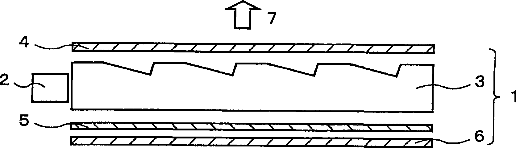
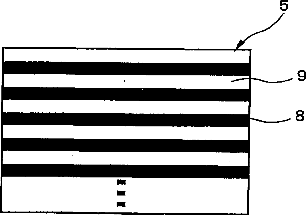
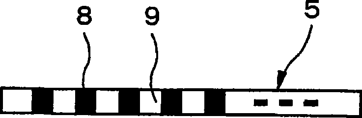
[0141] The beam direction adjuster having a transparent layer width L2 = 0.085 mm, a transparent layer refractive index n = 1.60, a light absorbing layer width L3 = 0.015 mm and a thickness D2 = 0.129 mm was manufactured, wherein the A1 reflective plate was Vapor deposition is on one side thereof and the light absorbing layer extends parallel to the light guiding direction of the light guiding plate. The beam direction adjuster, the linear light source, the light guide plate and the PNLC device were combined to manufacture the lighting device of the present invention as shown in FIG. 23 . In Figure 23, pairs with figure 1 and image 3 The same components are given the same reference numerals, and their detailed descriptions are omitted. results, such as Figure 24 As shown in , a distribution with a maximum exit light angle of 31° in the exit light angle control direction (direction perpendicular to the light guiding direction) is obtained for the transmission state of the...

example 2

[0143] The beam direction adjuster of Example 1, such as Figure 25A The shown light guide plate (inclination of outgoing light in the light guiding direction: β is approximately 43°), beam direction adjuster with a prism surface with an apex angle of 50° ( Figure 25B ), linear light source and PNLC device combination, to manufacture the lighting equipment of the present invention ( Figure 25C ). Figure 25C is similar to Figure 15 A modified configuration of the first exemplary embodiment shown in . As a result, for Figure 26 In the transmission state of the PNLC shown in , a distribution with a maximum outgoing light angle of 31.5° can be obtained in the outgoing light angle control direction (direction perpendicular to the light guiding direction) (the outgoing light angle distribution width M2=63°). Furthermore, when the liquid crystal display panel was attached to the lighting device of this embodiment, it was visually confirmed that there was no Murray effect / une...

example 3

[0145] The beam direction adjuster (second beam direction adjuster) of Comparative Example 1 is disposed between the beam direction adjuster and the PNLC device of the lighting device of Example 2, so that the light absorbing layer extends perpendicularly to the light guiding direction of the light guide plate, to manufacture lighting device( Figure 27 ). As a result, for the transmissive state of the PNLC as shown in FIG. Figure 28A ) in the direction of the maximum exit light angle 29 ° (-29 ° to +29 °) distribution, in the parallel direction ( Figure 28B ) with a distribution with a maximum exit light angle of 29° (-29° to +23°). Figure 27 The construction shown in the Figure 21B The configuration of the second exemplary embodiment shown in is the same.


PUM

PropertyMeasurementUnit
refractive indexaaaaaaaaaa
widthaaaaaaaaaa
widthaaaaaaaaaa

Abstract

A light source is arranged on a side of a light guide plate, and a beam direction regulating element and a reflecting plate are arranged in sequence on the light guide plate on the side opposite to the illuminating direction. On the illuminating direction side of the light guide plate, a transmission / scattering switching element is arranged. Light inputted to the light guide plate from the light source is outputted in a direction opposite to the illuminating direction, passes through the beam direction regulating element and is reflected by the reflecting plate. The reflected light passes through the beam direction regulating element again, passes through the light guide plate and is outputted as transmitted light or scattered light after entering the transmission / scattering switching element. Thus, generation of moire and luminance nonuniformity are suppressed and an illuminating apparatus which can control output light angular distribution is provided.

Description

technical field [0001] The present invention relates to a lighting device, a method for lighting and a display device capable of controlling the angle of outgoing light, and in particular to a thin, high-visibility lighting device, a display device for A backlight, and a display device including the lighting device. Background technique [0002] Recently, display panels are widely used in large terminals such as televisions, medium-sized terminals such as notebook-sized personal computers and cash dispensers, and small-sized terminals such as mobile phones and portable game machines. In particular, display devices using liquid crystal display panels have advantages such as thinness, lightness, and low power consumption, and are installed in many terminal devices. [0003] Traditionally, narrow viewing angles have been considered a disadvantage of liquid crystal display panels; but coplanar switching methods, vertical alignment modes, etc. have become practical; and currentl...

Claims


Application Information

Patent Timeline
Patent Type & Authority Applications(China)
IPC IPC(8): F21V8/00G02F1/13357G02B5/02F21Y101/02
CPCG02B5/045G02B6/0038G02B6/0053G02B5/02G02B6/0055
Inventor 斋藤悟郎今井雅雄
Owner NEC CORP
Why Eureka
Try Eureka