Light guide, illumination system, backlighting system and display device

a technology of backlighting system and light guide, which is applied in the direction of planar/plate-like light guide, lighting and heating apparatus, instruments, etc., can solve the problems of increasing weight, difficult to generate good uniformity, and considerable weight of light guide, so as to improve the uniformity of light, increase the spread of light when it enters the light guide part, and reduce the effect of light intensity

Inactive Publication Date: 2012-06-21
KONINKLIJKE PHILIPS ELECTRONICS NV
View PDF9 Cites 34 Cited by
  • Summary
  • Abstract
  • Description
  • Claims
  • Application Information

AI Technical Summary

Benefits of technology

[0014]In an embodiment of the light guide, the first light input window is positioned on a normal axis of the front wall of the second light guide part, and the second light input window is positioned on a normal axis of the front wall of the first light guide part. A normal axis typically is an imaginary axis being arranged perpendicular to a surface, in this case, perpendicular to the front wall of the first light guide part or second light guide part. In such an arrangement, the first light input window actually is positioned behind the second light guide part and the second light input window actually is positioned behind the first light guide part. This light guide has the advantage that it enables a relatively compact illumination system. This compact illumination system is especially enabled due to the availability of relatively small high power light sources such as emitting diodes which may be located at the light input window of the light guide parts, behind the neighboring light guide parts.
[0025]In an embodiment of the illumination system, the illumination system further comprises a luminescent material or comprises a mixture of luminescent materials for converting at least part of the light emitted by the light source into light having a longer wavelength. The luminescent material may, for example, be arranged on the front wall and / or on the rear wall of the light guide or may be arranged on a separate substrate arranged between the light source and the light output window. Alternatively the luminescent material may be arranged on the light output window. Such an arrangement of the luminescent material is also known as a remote phosphor arrangement. The benefit when having the luminescent material remote from the light source is that the efficiency of the luminescent material is improved, the range of luminescent materials to choose from is improved due to the lower temperature requirements of the luminescent material in the remote phosphor arrangement, and the remote luminescent material also acts as a diffuser layer which diffuses the light emitted by the light source avoiding the use of a separate diffuser.

Problems solved by technology

A drawback of this edge-lit configuration, especially for relatively large display devices, is that the weight of the light guide is considerable and that it is relatively difficult to generate a good uniformity especially at an area of the large light output window where the light is coupled into the light guide.
However, these wedge-shaped light guides further increase the weight and are also relatively difficult to manufacture for large light output windows and thus expensive.
Furthermore, the arrangement of the light sources at the edge wall of the light guide generally generates a relatively broad and thick rim around the display device which, next to the less aesthetic appearance of the display, also requires additional space when, for example, integrating the display device in a further application or housing.
So a drawback of this known illumination system is that the illumination system is relatively thick, especially at the edge region of the illumination system.

Method used


Image

  • Light guide, illumination system, backlighting system and display device
  • Light guide, illumination system, backlighting system and display device
  • Light guide, illumination system, backlighting system and display device

Examples


first embodiment

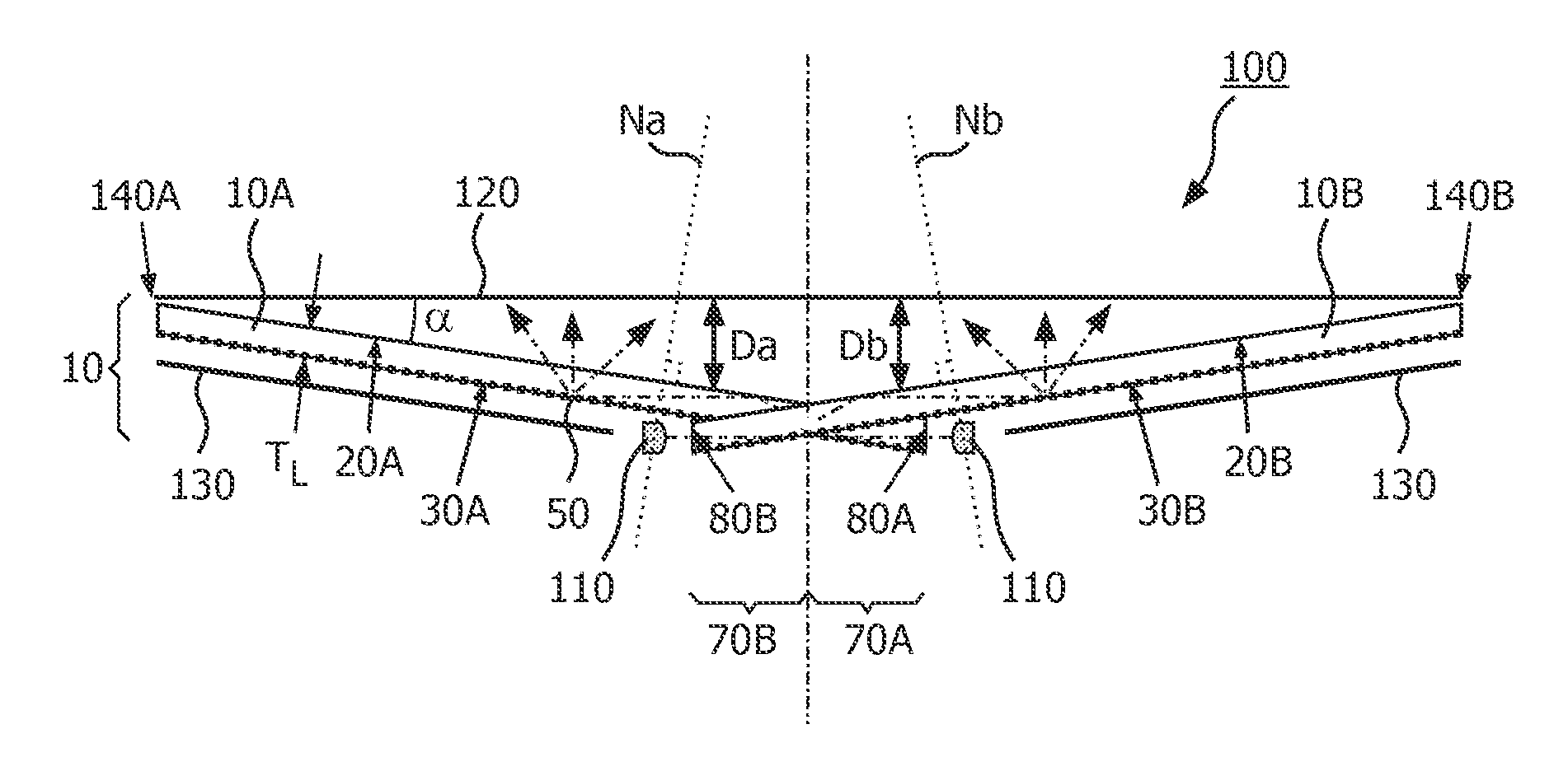
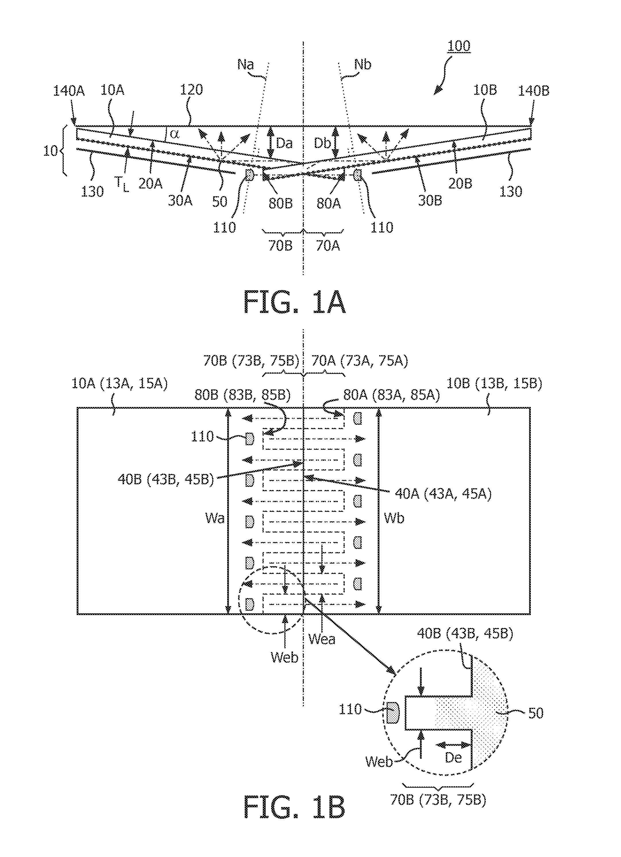
[0036]FIG. 1A is a simplified cross-sectional view of the illumination system 100 comprising the light guide 10 according to the invention. The light guide 10 comprises a first light guide part 10A and a second light guide part 10B, each having a front wall 20A, 20B, a rear wall 30A, 30B arranged opposite the front wall 20A, 20B and edge walls 40A, 40B (see FIG. 1B) between the front wall 20A, 20B and the rear wall 30A, 30B. The first light guide part 10A and the second light guide part 10B each are arranged for guiding light in a direction substantially parallel to the front wall 20A, 20B (indicated in the figures with a dash-dot-dot-line or with a dash-dot-dot-arrow) and each further comprises light-extraction means 50 for extracting at least part of the guided light via the front wall 20A, 20B. The first light guide part 10A comprises a first light guide extension 70A which extends from a first edge wall 40A (see FIG. 1B) of the first light guide part 10A. The first light guide e...

second embodiment

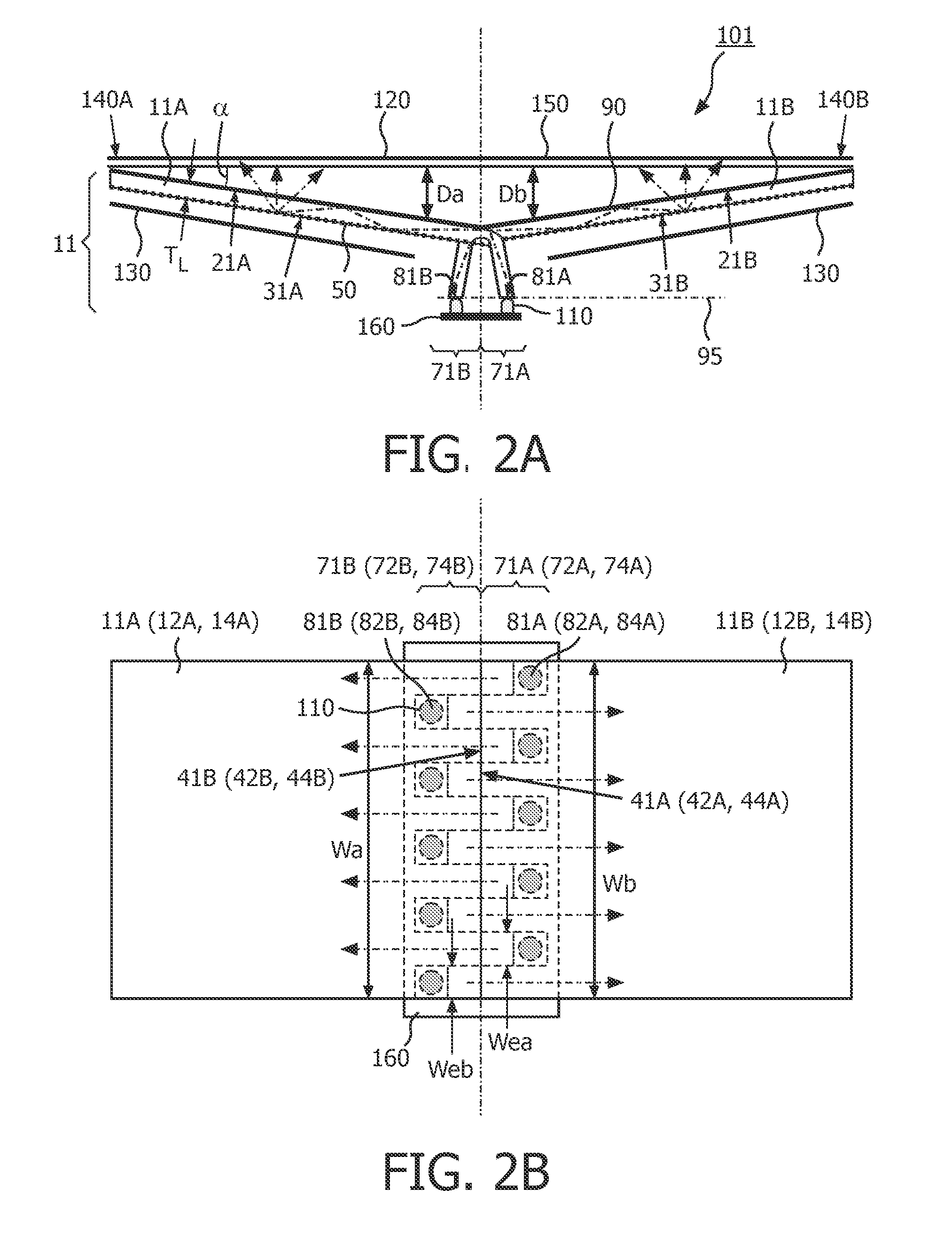
[0047]FIG. 2A is a simplified cross-sectional view of the illumination system 101 comprising the light guide 11 according to the invention. In the embodiment shown in FIG. 2, the light guide extension 71A, 71B of the light guide 11 is curved away from the light output window 120. This curved part of the light guide extension 71A, 71B causes the light input window 81A, 81B of the first light guide part 11A and the second light guide part 11B to be arranged substantially parallel to the light output window 120. In the embodiment shown, a single light source 110 may be sufficient to provide the light into the first light guide part 11A, and the second light guide part 11B. In the schematic cross-sectional view shown in FIG. 2A, the curvature of the light guide extension 71A, 71B positions the first light input window 81A and the second light input window 81B to coincide with a same imaginary plane 95. In such an arrangement, the imaginary plane 95 may, for example, be parallel to the l...

sixth embodiment

[0052]FIGS. 3A to 3D are simplified cross-sectional views of a third to sixth embodiment of the illumination system 102, 103, 104, 105 comprising the light guide 12, 13, 14, 15 according to the invention. Each light guide 12, 13, 14, 15, 16 is constituted by a first light guide part 12A, 13A, 14A, 15A which comprises a front wall 22A, 23A, 24A, 25A and a rear wall 32A, 33A, 34A, 35A, and by a second light guide part 12B, 13B, 14B, 15B which comprises a front wall 22B, 23B, 24B, 25B and a rear wall 32B, 33B, 34B, 35B. In the sequence of embodiments shown in FIGS. 3A to 3D, the front wall 22A, 23A, 24A, 25A, 22B, 23B, 24B, 25B of the light guide parts 12A, 13A, 14A, 15A, 12B, 13B, 14B, 15B all are substantially parallel to the light output window 120 of the illumination system 102, 103, 104, 105. This enables that the illumination system 102, 103, 104, 105 remains relatively thin at the edges of the light output window 120 and actually enables that the whole illumination system 102, 1...


PUM


Abstract

The invention relates to a light guide (10) for illuminating a light output window (120) of an illumination system (100), the illumination system, a backlighting system (100) and a display device (200). The light guide comprises a first light guide part (10A) comprising a first light guide extension (70A) extending from a first edge wall (40A) of the first light guide part (10A), and comprises a second light guide part (10B) comprising a second light guide extension (70B) extending from a second edge wall (40B) of the second light guide part (10B), the first light guide extension (70A) being configured for positioning a first light input window (80A) at a side of the second light guide part (10β) facing a rear wall (30B) of the second light guide part (10B), the second light guide extension (70B) being configured for positioning a second light input window (80B) at a side of the first light guide part (10A) facing the rear wall (30A) of the first light guide part. An effect of the light guide according to the invention is that due to the configuration of the first light guide extension and the second light guide extension, the first light input window of the first light guide part is arranged behind the second light guide part, and the second light input window of the second light guide part is arranged behind the first light guide part.

Description

FIELD OF THE INVENTION[0001]The invention relates to a light guide for illuminating a light output window of an illumination system.[0002]The invention also relates to an illumination system, a backlighting system and a display device.BACKGROUND OF THE INVENTION[0003]Light guides for illuminating a light output window of the illumination system are known per se. They are used, inter alia, in general illumination systems and in backlighting systems for (picture) display devices, for example, for TV sets and monitors. Such light guides are particularly suitable for use as backlighting systems for non-emissive display devices such as liquid crystal display devices, also denoted as LCD panels, which are used in, for example, (portable) computers or, for example, (portable) telephones.[0004]Said non-emissive display devices usually comprise a substrate provided with a regular pattern of pixels which are each controlled by at least one electrode. The display device utilizes a control circ...

Claims


Application Information

Patent Timeline
Patent Type & Authority Applications(United States)
IPC IPC(8): G09F13/04F21V7/00F21V8/00
CPCG02B6/0028G02B6/0088G02B6/008G02B6/00G02B6/0001G02F1/1335
Inventor PIJLMAN, FETZEVAN HERPEN, MAARTEN MARINUS JOHANNES WILHELMVAN BAARDWIJK, MENNO
Owner KONINKLIJKE PHILIPS ELECTRONICS NV
Why Eureka
Try Eureka