
Detection device, detection program, detection method, vehicle equipped with detection device, parameter calculation device, parameter calculating parameters, parameter calculation program, and method of calculating parameters

a detection device and image technology, applied in scene recognition, television systems, instruments, etc., can solve the problem of not clearly dividing a person in an image into a number of segments having different sizes, and achieve the effect of correct detection of the presence of the person

Inactive Publication Date: 2015-12-03
DENSO CORP
View PDF18 Cites 29 Cited by
  • Summary
  • Abstract
  • Description
  • Claims
  • Application Information

AI Technical Summary

Benefits of technology

The detection device described in this patent uses a neural network process to accurately detect the presence of a person in an image, even if they are hidden by other objects. This is achieved by analyzing segments of a sample image that contain at least a part of the person and using these parameters in the neural network process. This method allows for high accuracy in detecting people, even if they are only partially visible.

Problems solved by technology

In order to assist a driver of an own vehicle to drive safety, there are various technical problems.
One of the problems is to correctly and quickly detect one or more pedestrians in front of the own vehicle.
However, this method does not clearly indicate dividing a person in the image into a number of segments having different sizes.

Method used


Image

  • Detection device, detection program, detection method, vehicle equipped with detection device, parameter calculation device, parameter calculating parameters, parameter calculation program, and method of calculating parameters
  • Detection device, detection program, detection method, vehicle equipped with detection device, parameter calculation device, parameter calculating parameters, parameter calculation program, and method of calculating parameters
  • Detection device, detection program, detection method, vehicle equipped with detection device, parameter calculation device, parameter calculating parameters, parameter calculation program, and method of calculating parameters

Examples


first exemplary embodiment

[0055]A description will be given of a first exemplary embodiment with reference to FIG. 1 to FIG. 13.

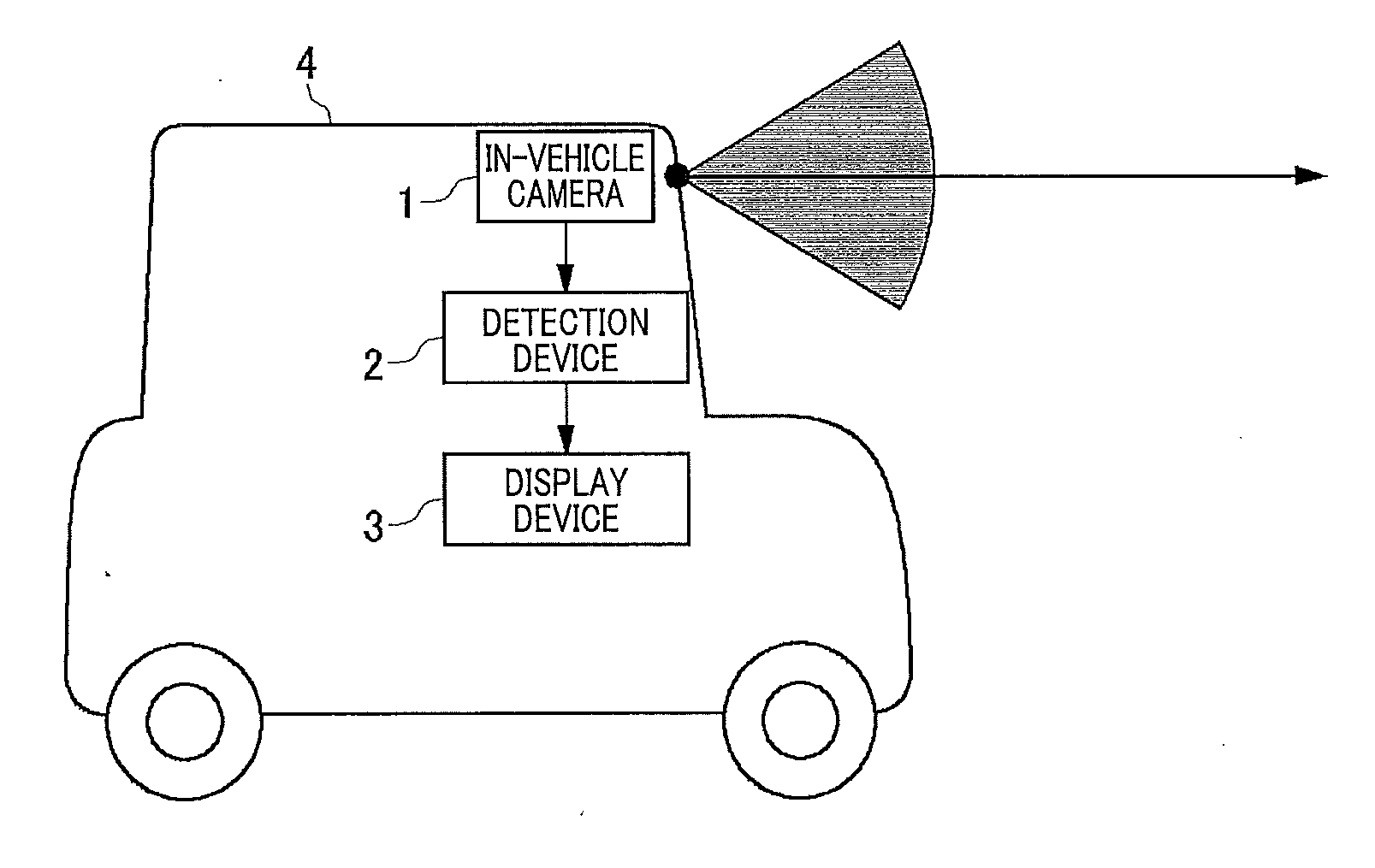
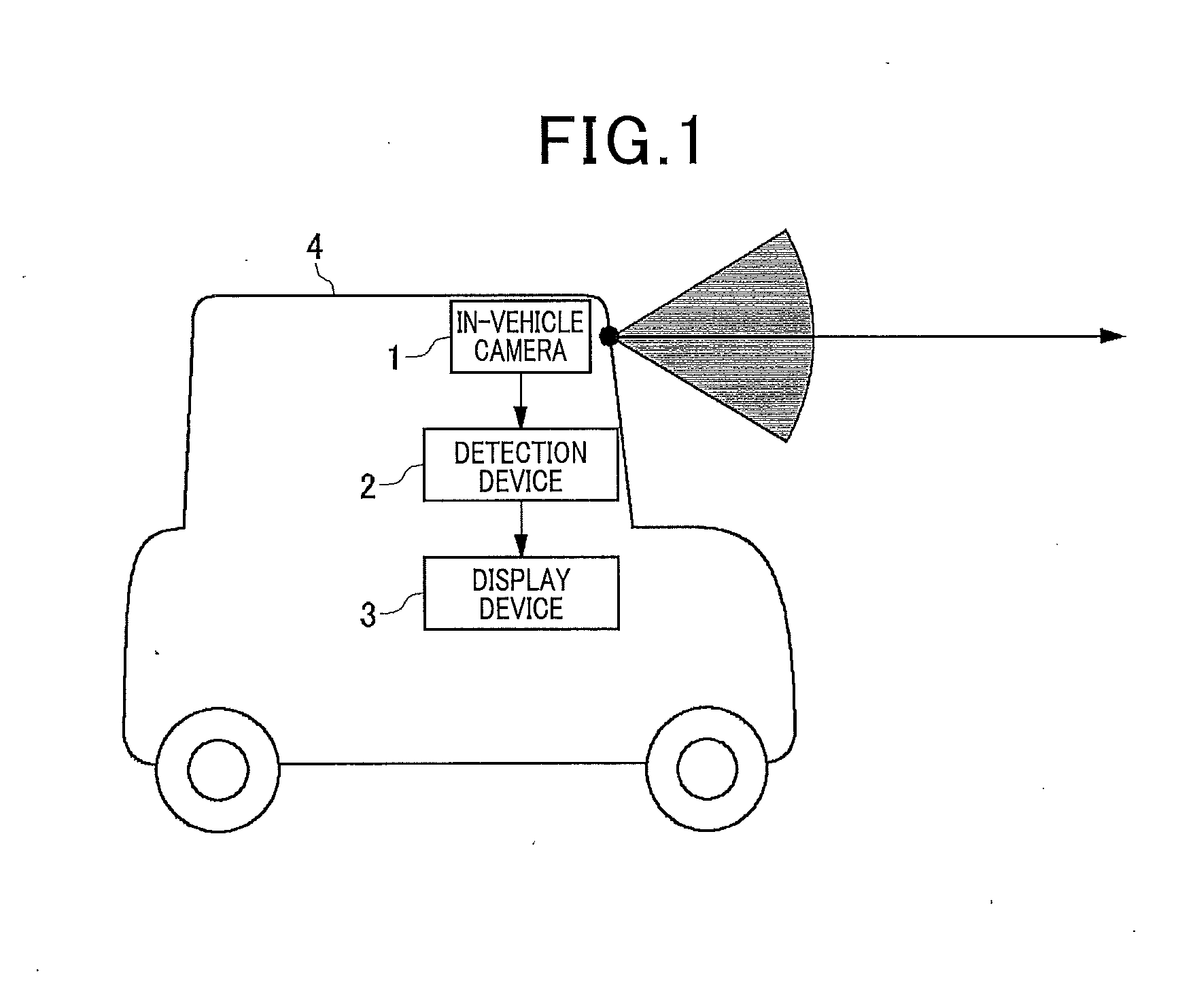
[0056]FIG. 1 is a view showing a schematic structure of a motor vehicle equipped with an in-vehicle camera 1, a detection device 2, a display device 3, etc. according to the first exemplary embodiment.

[0057]The in-vehicle camera 1 is mounted in the own vehicle so that an optical axis of the in-vehicle camera 1 is toward a horizontal direction, and the in-vehicle camera 1 is hidden in a driver of the own vehicle. For example, the in-vehicle camera 1 is arranged on the rear side of a rear-view mirror in a vehicle body 4 of the own vehicle. It is most preferable for a controller (not shown) to always direct the in-vehicle camera1 to the horizontal direction with high accuracy. However, it is acceptable for the controller to direct the optical axis of the in-vehicle camera to the horizontal direction approximately. The in-vehicle camera 1 obtains an image of a front view scene of the ow...

second exemplary embodiment

[0177]A description will be given of the detection device 2 according to a second exemplary embodiment with reference to FIG. 14, FIG. 15A and FIG. 15B. The detection device 2 according to the second exemplary embodiment has the same structure as the detection device 2 according to the first exemplary embodiment previously described.

[0178]The detection device 2 according to the second exemplary embodiment corrects the distance D between the in-vehicle camera 1 (see FIG. 1) and a person (pedestrian) on the basis of detection results using a plurality of frames (frame images) obtained in the input images transmitted from the in-vehicle camera 1.

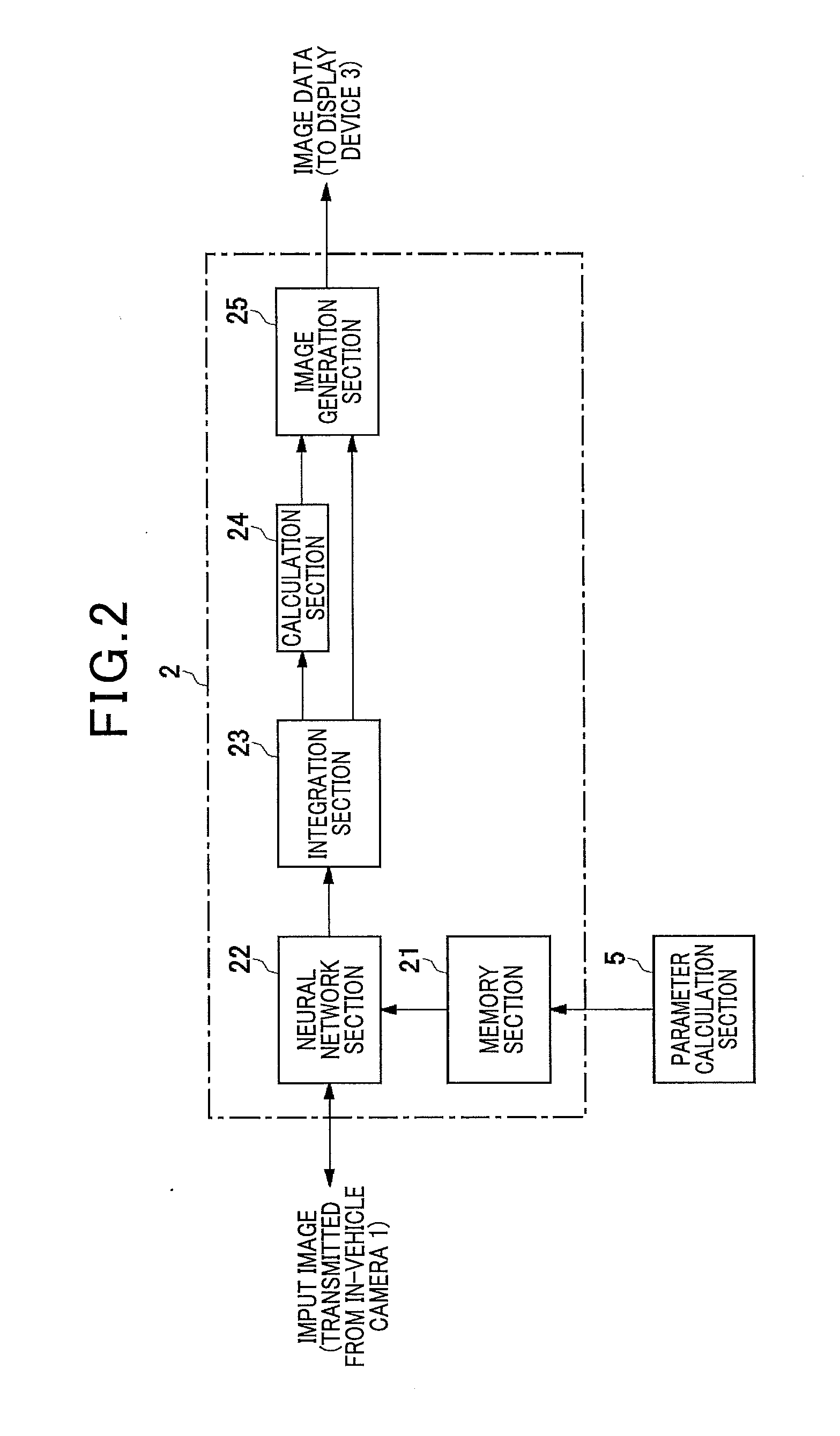
[0179]The neural network processing section 22 and the integration section 23 in the detection device 2 shown in FIG. 2 specify the central position pc of the person, the upper end position pt of the person, and the lower end position pb of the person in the input image transmitted from the in-vehicle cameral 1. As can be understood from the eq...


PUM


Abstract

A detection device has a neural network process section performing a neural network process using parameters to calculate and output a classification result and a regression result of each of frames in an input image. The classification result shows a presence of a person in the input image. The regression result shows a position of the person in the input image. The parameters are determined based on a learning process using a plurality of positive samples and negative samples. The positive samples have segments of a sample image containing at least a part of the person and a true value of the position of the person in the sample image. The negative samples have segments of the sample image containing no person.

Description

CROSS-REFERENCE TO RELATED APPLICATION[0001]This application is related to and claims priority from Japanese Patent Applications No. 2014-110079 filed on May 28, 2014, and No. 2014-247069 filed on Dec. 5, 2014, the contents of which are hereby incorporated by reference.BACKGROUND OF THE INVENTION[0002]1. Field of the Invention[0003]The present invention relates to detection devices capable of detecting a person such as a pedestrian in an image, and detection programs and detection methods thereof. Further, the present invention relates to vehicles equipped with the detection device, parameter calculation devices capable of calculating parameters to be used by the detection device, and parameter calculation programs and methods thereof.[0004]2. Description of the Related Art[0005]In order to assist a driver of an own vehicle to drive safety, there are various technical problems. One of the problems is to correctly and quickly detect one or more pedestrians in front of the own vehicle...

Claims


Application Information

Patent Timeline
Patent Type & Authority Applications(United States)
IPC IPC(8): G06K9/00G06K9/66H04N5/14G06K9/62
CPCG06K9/00369H04N5/144G06K9/66G06K9/6267G06V40/103G06V10/454G06V20/58G06F18/24
Inventor TAMATSU, YUKIMASAYOKOI, KENSUKESATO, IKURO
Owner DENSO CORP
Learn More