
Apparatus for transmitting and receiving downlink data in wireless communications system supporting cooperation between transmission points and method therefor

wireless communication technology, applied in the field of apparatus and a wireless communication system for transmitting and receiving downlink data, can solve problems such as waste of resources, and achieve the effects of improving wireless communication services, high data reception rate, and enhancing the information reception rate of the terminal

Active Publication Date: 2015-12-03
SAMSUNG ELECTRONICS CO LTD
View PDF4 Cites 6 Cited by
  • Summary
  • Abstract
  • Description
  • Claims
  • Application Information

AI Technical Summary

Benefits of technology

The present invention improves wireless communication for terminals located at the edge of a cell in a cellular wireless communication system by introducing inter-cell cooperative transmission (CoMP). This enhances the data reception rate for all terminals in the cell regardless of their locations. Additionally, the invention provides faster and more reliable information reception for terminals located at the edge of a cell by allowing multiple cells to simultaneously transmit information to the terminal. The invention also improves the efficiency of data transmission and reception by recognizing a specific type of CSI-RS resource and utilizing it for effective downlink data transmission and reception. Overall, the invention improves overall wireless communication performance and quality.

Problems solved by technology

In addition, in a good channel state, the transmitter may increase the amount of transmission data to effectively transmit a lot of information while maintaining the reception error probability within a desired level.
However, in the current LTE-A system, since the PDSCH signals are received on the assumption that the downlink data is not mapped in all of the CSI-RS resources allocated to the terminal, the allocation of a plurality of CSI-RSs may cause a waste of resources.

Method used


Image

  • Apparatus for transmitting and receiving downlink data in wireless communications system supporting cooperation between transmission points and method therefor
  • Apparatus for transmitting and receiving downlink data in wireless communications system supporting cooperation between transmission points and method therefor
  • Apparatus for transmitting and receiving downlink data in wireless communications system supporting cooperation between transmission points and method therefor

Examples


embodiment 1

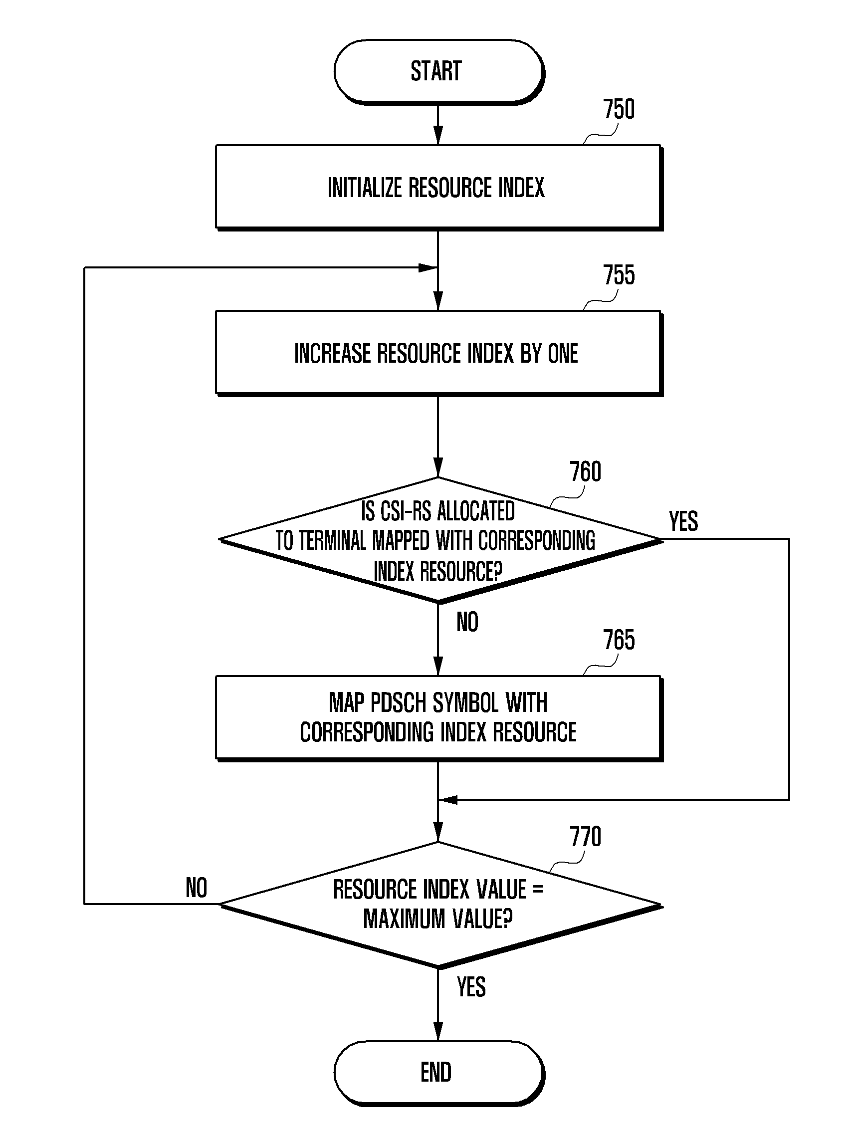
[0079]A method of simply defining the PDSCH transmission resource in the case of a plurality of CSI-RS resources allocated to the resource block is to define that the PDSCH is not transmitted to all of the time frequency resources allocated with the CSI-RS resources.

[0080]FIG. 6 illustrates Embodiment 1 in which PDSCH symbols are mapped. Referring to FIG. 6, the central control device may map the PDSCH symbols, i.e., the data, in an order of the index from the lowest one to the highest one such that: the resource positions, where the CSI-RSs (CSI-RS-1, and CSI-RS-2) allocated to the terminal are mapped, are skipped, and the next PDSCH symbol is mapped with the next frequency resource. Here, the CSI-RSs (CSI-RS-1, and CSI-RS-2) allocated to the terminal may be the CSI-RSs corresponding to the resource management set mentioned above.

[0081]The method in which the PDSCH symbols are mapped in sequence while skipping specific resources may be referred to as a rate matching method. That is...

embodiment 2

[0090]As the second method for defining the PDSCH transmission resource in the case of a plurality of CSI-RS resources allocated to the resource block transmitted to the terminal, the rate matching method mentioned above may be applied to the CSI-RS resources included in the CoMP measurement set, and the PDSCH symbols may be mapped with positions of the CSI-RS resources that are not included in the CoMP measurement set.

[0091]FIG. 8 illustrates Embodiment 2 for mapping the PDSCH symbols. Referring to FIG. 8, the central control device may map the PDSCH symbols in an order of the index from the lowest one to the highest one, and if a specific index resource corresponds to the CSI-RS resource (CSI-RS-3) allocated to the terminal and belongs to the CoMP measurement set, may skip the PDSCH symbol ma-Ting with respect to the corresponding resource so that the next PDSCH symbol is mapped with the next frequency resource.

[0092]On the contrary, if the time frequency resource of a specific in...

embodiment 3

[0156]As the third method for defining the PDSCH transmission resource in the case of a plurality of CSI-RS resources allocated to the resource block transmitted to the terminal, the central control device may directly configure whether or not the rate matching is applied to a specific CSI-RS resource using the RRC signal, and may determine the PDSCH resource mapping according thereto.

[0157]FIG. 10 illustrates Embodiment 3 for mapping the PDSCH symbols. Referring to FIG. 10, the central control device may map the PDSCH symbols in an order of the index from the lowest one to the highest one, and if a specific index resource corresponds to the CSI-RS resource (CSI-RS-5) allocated to the terminal and if the CSI-RS is configured to apply the rate matching through the RRC signal, the central control device may skip the PDSCH symbol mapping with respect to the corresponding index resource so that the next PDSCH symbol is mapped with the next frequency resource.

[0158]On the contrary, if th...


PUM


Abstract

Disclosed are an apparatus for transmitting and receiving a downlink data in a wireless communications system supporting cooperation between transmission points and a method therefor. A method for transmitting a downlink data in a wireless communications system includes the steps of: transmitting the information on resources management collection including the CSI-RS information for measuring the terminal received bower to a terminal; receiving a report of the received power measurement of the CSI-RS corresponding to the resources management collection from the terminal; determining the measurement collection including the CSI-RS information for the terminal to infer a channel based on the received power measurement report; and transmitting the resources mapped with data to the terminal based on the measurement collection.

Description

TECHNICAL FIELD[0001]The present invention relates to an apparatus and a method for transmitting and receiving downlink data in a wireless communication system that adopts a cooperative multi-point (COMP) scheme.BACKGROUND ART[0002]A wireless communication system has been developed into a high speed and high quality wireless packet data communication system to provide a data service and a multimedia service as well as a basic voice service. Recently, various wireless communication standards, such as high speed downlink packet access (HSDPA), high speed uplink packet access (HSUPA), long term evolution (LTE), or long term evolution advanced (LTE-A) in 3GPP, high rate packet data (HRPD) in 3GPP2, or IEEE 802.16, have been developed to support the high speed and high quality wireless packet data transmission service.[0003]The LTE system, which has been developed to effectively support the high speed wireless packet data transmission, may maximize the capacity of the wireless system by ...

Claims


Application Information

Patent Timeline
Patent Type & Authority Applications(United States)
IPC IPC(8): H04W72/04H04B7/06
CPCH04W72/0406H04W72/0453H04W72/085H04B7/0626H04L5/0007H04L5/005H04L5/0035H04L5/0073H04B7/024H04W72/542H04W72/23H04W24/10H04W72/12H04W72/20
Inventor LEE, HYOJINKIM, YOUNSUNKIM, YOUNGBUMCHO, JOONYOUNGJI, HYOUNGJU
Owner SAMSUNG ELECTRONICS CO LTD
Learn More