Device for controlling the charge of an aerosol post-discharge

a technology of charge and aerosol, which is applied in the direction of electrostatic charge, vapor flow control, chemistry apparatus and processes, etc., can solve the problems of high cost of radioactive devices, strict use conditions, and modification of the shape and nature of electrodes, so as to achieve the effect of little or no toxic was

Inactive Publication Date: 2015-12-10
CENT NAT DE LA RECHERCHE SCI
View PDF5 Cites 2 Cited by
  • Summary
  • Abstract
  • Description
  • Claims
  • Application Information

AI Technical Summary

Benefits of technology

[0008]The invention makes it possible to palliate the aforementioned drawbacks by proposing a device for controlling the charge of an aerosol not using

Problems solved by technology

However, apart from the high cost of these radioactive devices, the legislative restrictions associated with their use are strict (permission required, requirement for a person with radioprotection skills, regular monitoring of the tightness of the source, and treatment of radioactive waste.)
However, in this type of device, the electrodes are in contact with the aerosol: a fraction of the aerosol

Method used


Image

  • Device for controlling the charge of an aerosol post-discharge
  • Device for controlling the charge of an aerosol post-discharge
  • Device for controlling the charge of an aerosol post-discharge

Examples


third embodiment

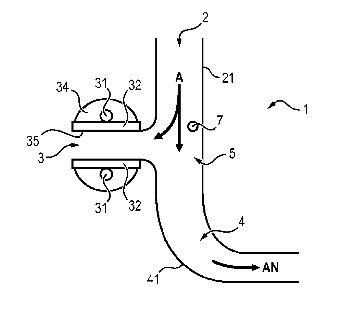
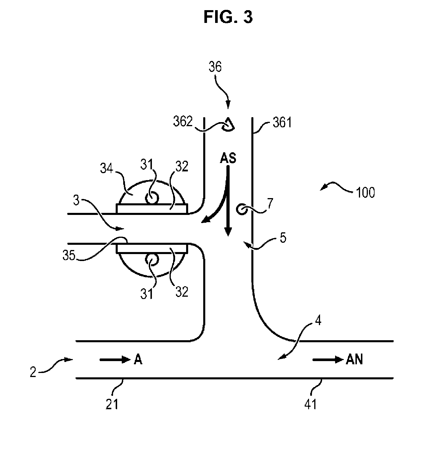
[0042]Relative to FIGS. 1, 2, 3, a device 1, 10, 100, for controlling the charge of an aerosol according to a first, a second, and the invention comprises a discharge area 3 having a dielectric barrier, a first duct 21 defining an inlet area 2 of an aerosol A, a second duct 41 defining a mixing area 4, and a post-discharge area 5 located at the junction between the first duct 21, the second duct 41 and the discharge area 3.

[0043]Advantageously, the discharge area 3 having an electric barrier is composed of two plates 32 of dielectric material defining a third duct 35 and two main metal electrodes 31, each connected to a plate 32 of dielectric material. The dielectric material forming the plates is for example alumina, and the contacts 34 between the main metal electrodes 31 and the dielectrics 32 are made of an insulating material, for example a silicone paste with high dielectric strength. This makes it possible to avoid the presence of parasitic discharges which could occur outsid...

first embodiment

[0047]According to a device 1 for controlling the charge of an aerosol A, relating to FIG. 1, the discharge area 3 and the inlet area 2 of the aerosol A are arranged one relating to the other in such a way that the mixing of the charged species and the particles is carried out in the post-discharge area to avoid fouling the discharge area 3, which is critical for the stability of the source of charged species. The charged species leave the discharge area 3 by electrostatic self-repulsion against the stream. Specifically, the charged species of one and the same polarity repel each other, making it possible to extract a portion of the charged species produced in the post-discharge area 5 despite the stream of aerosol A.

[0048]The stream of aerosol A is injected into the first duct 21. This stream of aerosol A is separated in two. A portion of the stream of aerosol A is injected into the discharge area 3 to drive the gaseous effluent and prevent it from leaving the discharge area 3 on t...

second embodiment

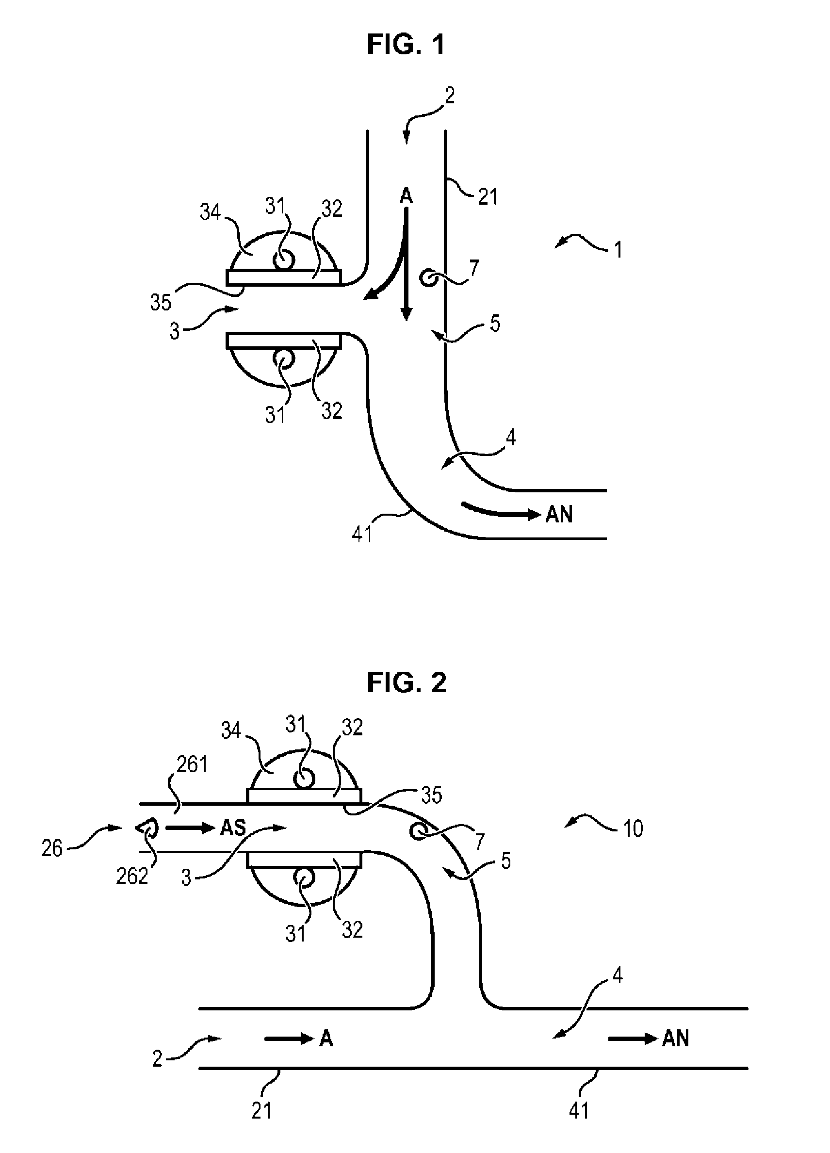
[0051]According to a device 10 for controlling the charge of an aerosol, described relative to FIG. 2, the charged species generated in the discharge area 3 are driven toward the post-discharge area 5 by a stream of dry air AS.

[0052]In this second embodiment, apart from the elements described in relation to FIG. 1, the device 10 further comprises a fourth duct 261 opening into the discharge area 3 and defining a dry air AS inlet area 26 linked to the discharge area 3.

[0053]In order to inject the dry air AS into the duct 261, the device 10 according to the second embodiment comprises an injection nozzle 262 adapted for being coupled with a dry air source (not represented) and positioned at the inlet of the duct 261. The air injected by the nozzle 262 into the duct 261 passes into the duct 35 defined by the plates 32 of dielectric material. In this second embodiment, the charged species generated in the discharge area 3 are driven by the stream of dry air AS toward the mixing area 4. ...


PUM


Abstract

The invention concerns a device for controlling the charge of an aerosol comprising: —an aerosol inlet area; —a discharge area having dielectric barriers, in which charged species are generated, the discharge area and the aerosol inlet area being arranged relative to one another in such a way that the aerosol introduced in this way does not flow via the discharge area; —a mixing area for mixing the aerosol with a portion of the charged species from the discharge area; —a post-discharge area linked to the discharge area, the aerosol inlet area and the mixing area being arranged in such a way that at least a portion of a stream flowing in the post-discharge area drives at least a portion of the charged species formed in the discharge area and expelled from the discharge area by electrostatic repulsion towards said mixing area.

Description

FIELD OF THE INVENTION[0001]The present invention relates to a device for controlling the charge of an aerosol and more particularly relates to a device for controlling the charge of an aerosol using dielectric barrier discharges.PRIOR ART[0002]An aerosol is a collection of particles, solid or liquid, of a chemical substance or a mixture of chemical substances in suspension in a gaseous medium. The term “neutralized aerosol” is an aerosol wherein the mean charge of the particles in suspension is almost zero (i.e. an elementary charge between −1 and +1) and when the distribution of the charge levels is of “Boltzmann” or “unimodal” type. The term “charged species” refers here to gas ions, positive and negative, and electrons.[0003]Devices are known for controlling the charge of an aerosol.[0004]Among these devices, radioactive devices are known that produce bipolar ions with equal densities for neutralizing an aerosol. However, apart from the high cost of these radioactive devices, th...

Claims


Application Information

Patent Timeline
IPC IPC(8): B03C3/36B03C3/38
CPCB03C3/38B03C3/361
Inventor BORRA, JEAN-PASCALJIDENKO, NICOLAS
Owner CENT NAT DE LA RECHERCHE SCI
Why Eureka
Try Eureka