Display device

a technology of a display device and a tape, which is applied in the direction of optics, instruments, optical light guides, etc., can solve the problems of deteriorating display quality, leaking outside light through these openings, and increasing manufacturing processes, so as to reduce the leaking light

Active Publication Date: 2015-12-10
TRIVALE TECH
View PDF10 Cites 1 Cited by
  • Summary
  • Abstract
  • Description
  • Claims
  • Application Information

AI Technical Summary

Benefits of technology

[0008]An object of the present invention is to provide a display device that reduces leaking light from an engagement portion between a housing and a backlight.

Problems solved by technology

There has been a problem that the light passing through these openings is propagated inside a production housing, which deteriorates display quality.
Moreover, there is also a problem that the light passing through these openings leaks outside.
However, there is a problem that sticking the tape increases manufacturing processes.
Moreover, there arises a problem that a material cost is increased by the tape.

Method used


Image

  • Display device
  • Display device
  • Display device

Examples


first preferred embodiment

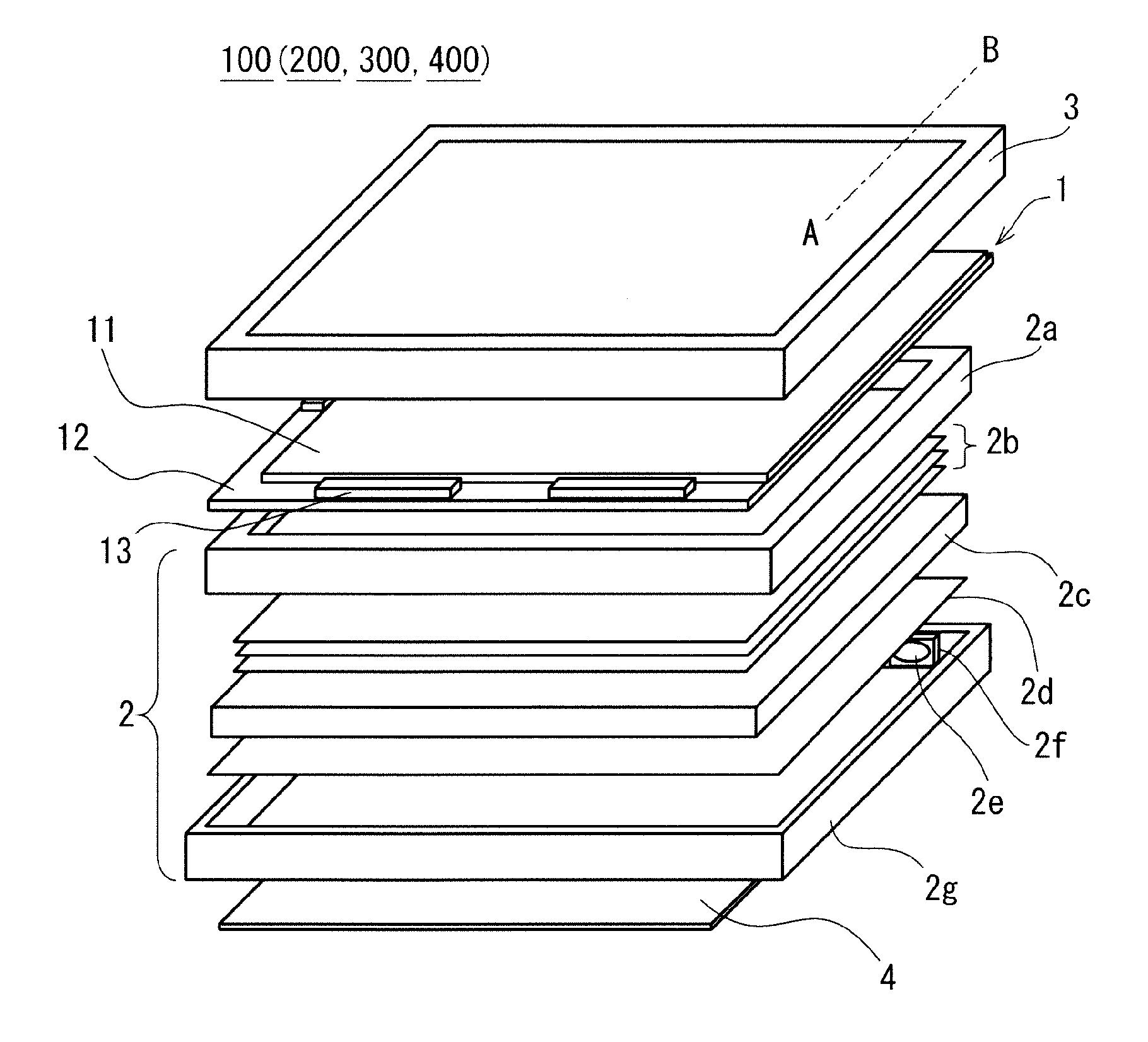
[0021]FIG. 1 is an exploded perspective view of a display device 100 in a first preferred embodiment. As shown in FIG. 1, the display device 100 includes a display panel 1, a backlight 2, a first housing 3, and a circuit board 4. The display panel 1 includes a liquid crystal display panel to display an image. The backlight 2 irradiates a back surface of the display panel 1 with planar light. The first housing 3 contains the display panel 1, the backlight 2, and the circuit board 4.

[0022]Moreover, on a front surface of the display panel 1, a touch panel to perform positional signal input to a screen from outside and an almost transparent protecting member to protect the touch panel (neither of which is shown) are provided. Moreover, on a back surface of the display device 100, a cover (not shown) to protect the circuit board 4 may be provided.

[0023]First, with a configuration of the display device 100, respective components will be described. The display panel 1 includes a transmissi...

second preferred embodiment

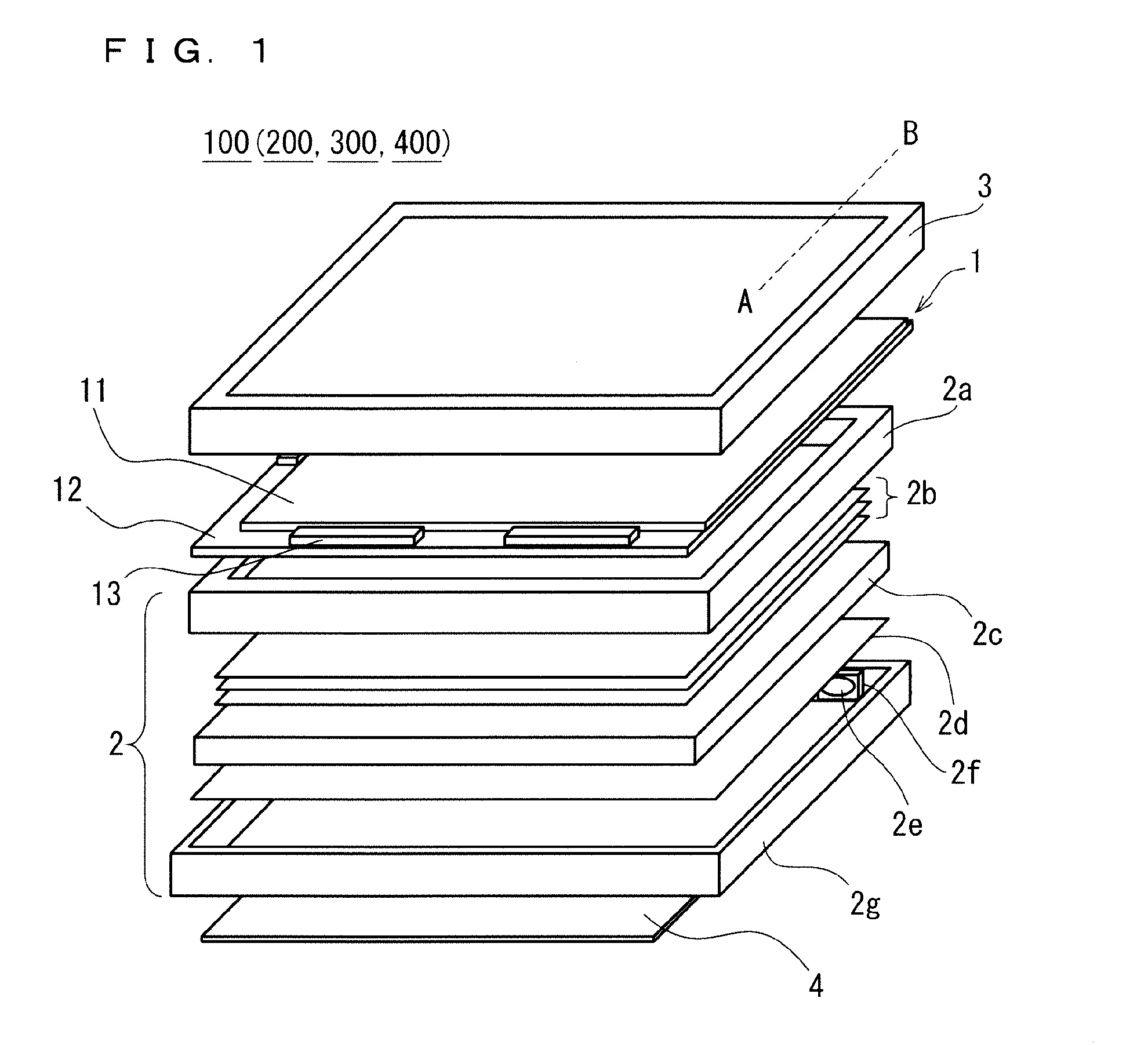
[0064]Hereinafter, a display device according to a second preferred embodiment is defined as a display device 200. FIG. 5 is a cross-sectional view of the display device 200 in the present second preferred embodiment along the line AB in FIG. 1. While FIG. 1 shows the exploded state, FIG. 5 shows an assembled state. FIG. 6 is a cross-sectional view along a line EF in FIG. 5.

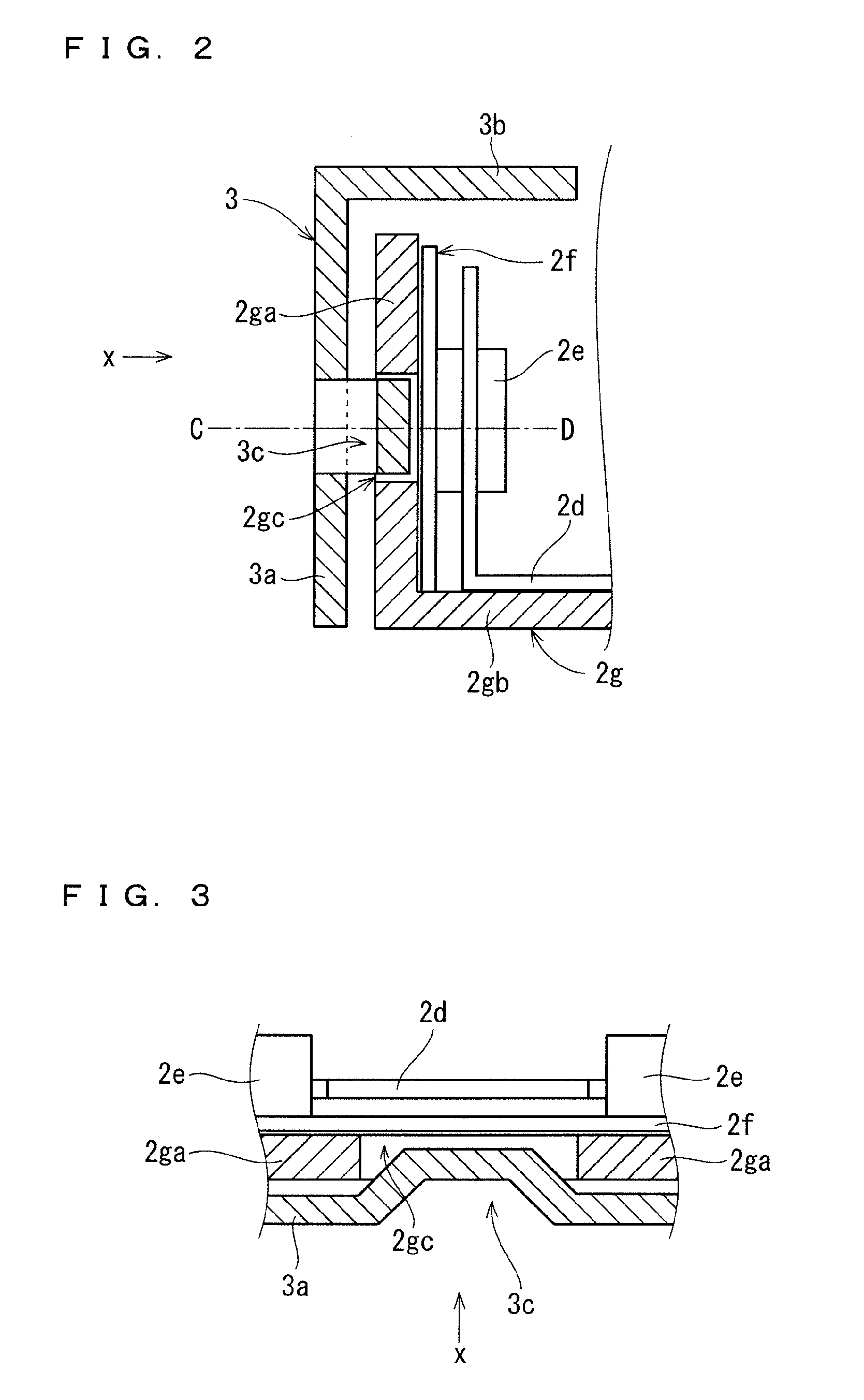
[0065]In the present second preferred embodiment, as shown in FIGS. 5 and 6, projected portions 3c provided in a second side wall portion 3a of a first housing 3 are formed by drawing press. In the present second preferred embodiment, each of the projected portions 3c, being formed by the drawing press, does not have a cutout as with each of the bridge-shaped projected portions 3c in the first preferred embodiment. The other configurations are the same as those in the first preferred embodiment, and thus, descriptions are omitted.

[0066]In the present second preferred embodiment, openings 2gc of a second housing 2...

third preferred embodiment

[0070]Hereinafter, a display device according to a third preferred embodiment is defined as a display device 300. FIG. 7 is a cross-sectional view of the display device 300 in the present third preferred embodiment along the line AB in FIG. 1. While FIG. 1 shows the exploded state, FIG. 7 shows an assembled state. FIG. 8 is a cross-sectional view along a line GH in FIG. 7.

[0071]In the present third preferred embodiment, as shown in FIGS. 7 and 8, projected portions 3c provided in a second side wall portion 3a of a first housing 3 each include a shear plane3ca. The projected portions 3c in the present third preferred embodiment are formed by drawing press. When the drawing press is performed, punching is performed to the shear plane 3ca so as to form the shear plane 3ca.

[0072]In the present third preferred embodiment, openings 2gc of a second housing 2g into which the projected portions 3c provided in the first housing 3 are fitted are provided at positions where they overlap a ligh...


PUM

PropertyMeasurementUnit
shapeaaaaaaaaaa
transparentaaaaaaaaaa
birefringenceaaaaaaaaaa

Abstract

A display device includes a first housing containing a display panel between a backlight and the first housing, the backlight includes a light source substrate, and a second housing that holds the light source substrate, the second housing includes a back surface portion and a first side wall portion protruded in a front surface direction of the backlight from the back surface portion, the light source substrate is fixed to an inside of the first side wall portion, an opening is provided in the first side wall portion so as to overlap the light source substrate, the first housing includes a front surface frame portion and a second side wall portion protruded in a back surface direction of the backlight from the front surface frame portion, a projected portion is provided in an inside of the second side wall portion, and the projected portion is fitted into the opening.

Description

BACKGROUND OF THE INVENTION[0001]1. Field of the Invention[0002]The present invention relates to a display device.[0003]2. Description of the Background Art[0004]With recent spread of information electronic equipment, a thin, lightweight display device has been used as a display for a portable telephone or a personal computer, various devices used for industrial applications, an in-vehicle display, a handy terminal, and an advertisement display in various fields.[0005]In the in-vehicle applications, the display devices are used all day and all night. A front surface housing (a cover) and a backlight making up a display device are fixed by respective engagement portions. A structure that fixes the front surface housing and the backlight is disclosed, for example, in Japanese Patent Application Laid-Open No. 2011-95533. According to an electrooptical device of Japanese Patent Application Laid-Open No. 2011-95533, obliquely upward hook portions are formed by cutting and raising work to...

Claims


Application Information

Patent Timeline
Patent Type & Authority Applications(United States)
IPC IPC(8): G02F1/1333G02F1/1335F21V8/00
CPCG02F1/133308G02F1/133512G02B6/009G02B6/0068G02B6/0093G02F2201/46G02F2201/465G02F1/133314G02F1/13332G02F1/133615
Inventor ARITA, KENJI
Owner TRIVALE TECH
Why Eureka
Try Eureka