Laser device

a laser device and laser technology, applied in the field of laser devices, can solve the problems of increasing the light intensity of light leaked in the cladding, the failure of the spot to be fitted in the core the increase of the light intensity of the transmission fiber, so as to reduce the light intensity of the leakag

Active Publication Date: 2020-06-25
PANASONIC INTELLECTUAL PROPERTY MANAGEMENT CO LTD
View PDF0 Cites 1 Cited by
  • Summary
  • Abstract
  • Description
  • Claims
  • Application Information

AI Technical Summary

Benefits of technology

[0009]The present disclosure makes it possible to reduce leak light in a transmission fiber, that is, light intensity of a laser beam directly incident on a cladding of the transmission fiber.

Problems solved by technology

However, the spot may fail to be fitted in the core of the transmission fiber because of misalignment of a focal position of the laser beam after the laser beam starts oscillating, increasing light intensity of light leaked in a cladding.
However, in the above-mentioned conventional configuration, when there is no enough margin in a core diameter of the transmission fiber with respect to a spot diameter of the laser beam, light intensity of leak light in the transmission fiber, that is, light intensity of light that fails to fit in the core of the transmission fiber to be leaked to the cladding increases due to misalignment of the focal position of the laser beam.
This increase in leak light may disadvantageously cause output drop of the laser beam transmitted by the transmission fiber or local heat generation near the incident end face of the transmission fiber.
In particular, accumulation of damage due to heat generation may disadvantageously result in breakage of the transmission fiber.

Method used


Image

  • Laser device
  • Laser device
  • Laser device

Examples


first exemplary embodiment

Configuration of Laser Device

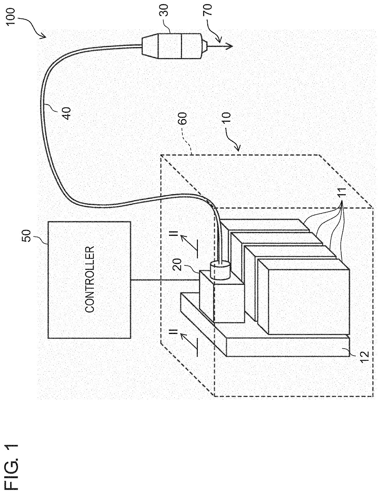
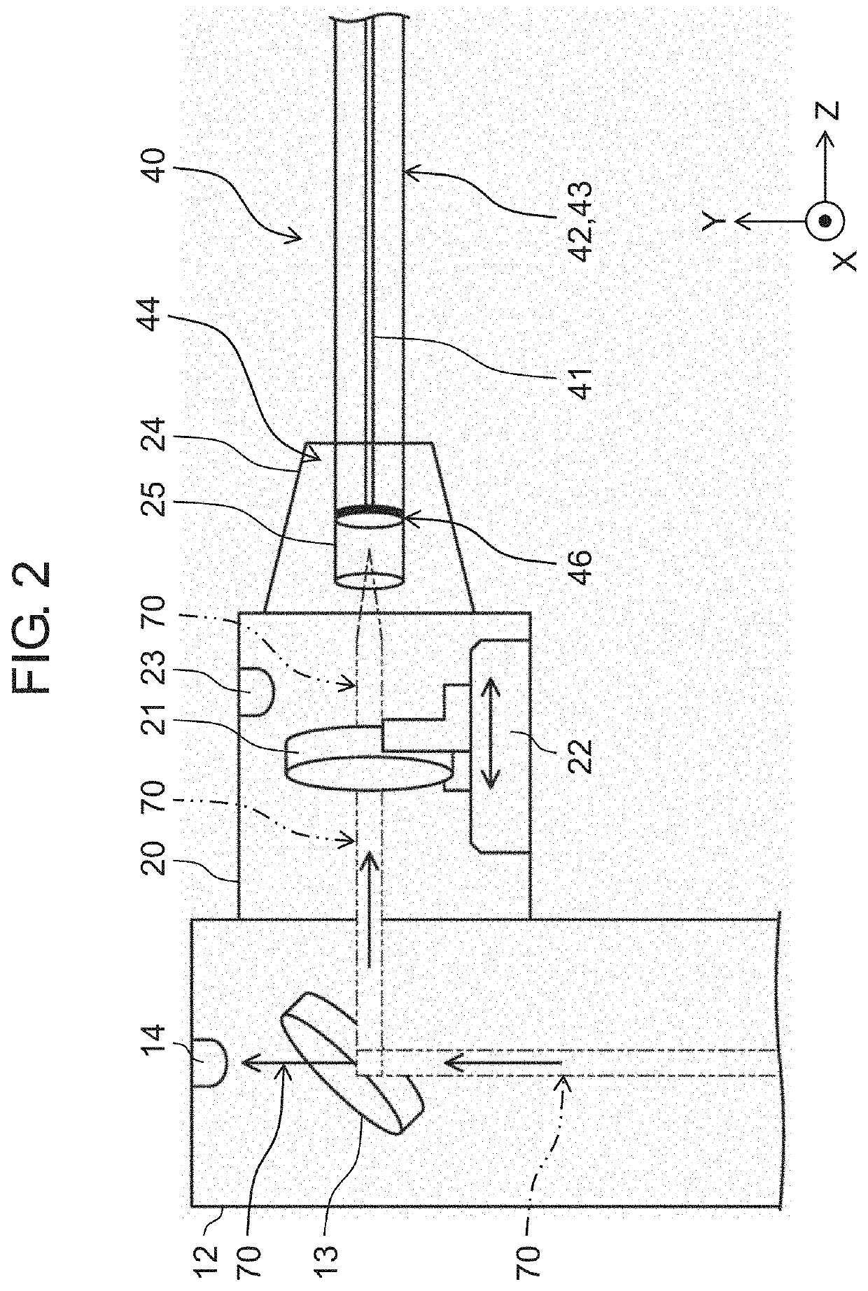
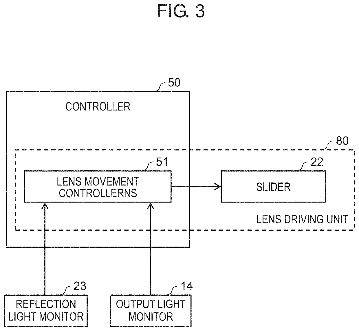
[0023]FIG. 1 is a configuration diagram of laser device 100 according to the present exemplary embodiment. FIG. 2 is a cross sectional schematic view along line II-II in FIG. 1. FIG. 3 is a functional block diagram of lens driving unit 80. Note that, in the following description, a direction of laser beam 70 toward partially transmissive mirror 13 in FIG. 2 may be referred to as a Y direction, a direction of laser beam 70 from partially transmissive mirror 13 toward transmission fiber 40 may be referred to as a Z direction, and a direction perpendicular to the Y direction and the Z direction may be referred to as an X direction. Note that the Z direction matches an optical axis direction of laser beam 70 emitted from condenser lens unit 20 within a range of assembly tolerance of an optical system of laser device 100.

[0024]As illustrated in FIG. 1, laser device 100 includes laser oscillator 10, condenser lens unit 20, laser beam emission head 30, transmis...

second exemplary embodiment

[0062]Laser device 100 according to the present exemplary embodiment basically has the same configuration as the configuration illustrated in the first exemplary embodiment, and a mode of movement control of condenser lens 21 during laser oscillation is different.

[0063]FIG. 9 illustrates a position adjustment procedure of condenser lens 21 according to the present exemplary embodiment. First, initial adjustment of the optical system such as the position of condenser lens 21 is performed before laser processing. Specifically, laser oscillation is performed by laser oscillator 10 to generate laser beam 70, and condenser lens 21 is moved by lens driving unit 80 to adjust the position of condenser lens 21 to determine an initial position of condenser lens 21 (step S1). In this case, laser oscillation time is adjusted such that exothermic temperature of condenser lens 21 due to laser beam 70 becomes less than or equal to a predetermined value. Also, in step S1, as illustrated in FIG. 4A,...


PUM

PropertyMeasurementUnit
core diameteraaaaaaaaaa
light intensityaaaaaaaaaa

Abstract

A laser device includes a laser oscillator that generates a laser beam, condenser lens that condenses laser beam emitted from the laser oscillator, transmission fiber that includes at least core that transmits laser beam condensed by condenser lens, and cladding provided around core, and a lens driving unit that adjusts a position of condenser lens. The lens driving unit automatically adjusts the position of condenser lens to reduce light intensity of laser beam incident on cladding.

Description

TECHNICAL FIELD[0001]The present disclosure relates to a laser device, and in particular, to a laser device that transmits a laser beam emitted from a laser oscillator to a transmission fiber using a condenser lens.BACKGROUND ART[0002]Recently, development of laser processing devices using direct diode laser (hereinafter, referred to as “DDL”) has accelerated with higher output of the DDL. By synthesizing laser beams emitted from a plurality of laser modules, the DDL can yield high output exceeding several kW. A laser beam emitted from a beam synthesizer is transmitted to a processing head placed at a predetermined position via a transmission fiber. In this context, the laser beam emitted from the beam synthesizer is condensed by a condenser lens, and a condensed spot of the condensed laser beam is reduced to a size to fit in a core of the transmission fiber on a laser beam incident end face (hereinafter, simply referred to as “incident end face”) of the transmission fiber to be inc...

Claims


Application Information

Patent Timeline
Patent Type & Authority Applications(United States)
IPC IPC(8): H01S3/034B23K26/70B23K26/064
CPCB23K26/064B23K26/707H01S3/034H01S3/067G02B6/4225G02B6/4206
Inventor DOMOTO, SHINYAKATO, NAOYAISHIKAWA, RYO
Owner PANASONIC INTELLECTUAL PROPERTY MANAGEMENT CO LTD
Why Eureka
Try Eureka