Projection type liquid crystal display and compensation plate

a liquid crystal display and compensation plate technology, applied in the field of projection, can solve the problems of not being able to compensate for such a change in the state, not being able to achieve the effect of improving contrast only insufficiently, and not being able to suppress leakage light sufficiently, so as to avoid interfacial reflection of incident light, and reduce leakage light toward the screen

Inactive Publication Date: 2009-04-02
SONY CORP
View PDF9 Cites 21 Cited by
  • Summary
  • Abstract
  • Description
  • Claims
  • Application Information

AI Technical Summary

Benefits of technology

[0013]In the projection type liquid crystal display of the embodiment, light emitted from the light source is polarization-split by the polarization beam splitter, and one of resultant polarization components of the light impinges upon the reflective liquid crystal element through the compensation plate. The incident light is modulated by the reflective liquid crystal element based on an image signal, and the modulated light impinges upon the projection means through the compensation plate and the polarization beam splitter. The incident light is projected upon a screen by the projection means to display an image based on the image signal. Since the in-plane retardation Re of the compensation plate is one-fourth the wavelength of light incident thereupon, the compensation plate serves as a quarter wave plate when viewed in the frontal direction of the display. As a result, an angular deviation of a polarization axis of light impinging upon the polarization beam splitter attributable to the impinging direction is suppressed, and leakage light toward the screen is reduced when black is displayed. The retardation RthL in the thickness direction of the compensation plate is equal to the retardation RthC in the thickness direction of the reflective liquid crystal element in absolute value and is the reverse of the retardation RthC in polarity. Therefore, the compensation plate cancels a minute phase difference in the reflective liquid crystal element. As a result, compensation is made for a change in the state of an angular deviation of a polarization axis of light modulated by the reflective liquid crystal element, whereby a further reduction in leakage light toward the screen is achieved when black is displayed. The single compensation plate provides the function of compensating for an angular deviation of a polarization axis and the function of compensating for a minute phase difference in the reflective liquid crystal element as thus described. It is therefore possible to avoid interfacial reflection of incident light which can occur, for example, when a quarter wave plate and a phase difference compensation plate are provided separately.
[0014]The compensation plate of the embodiment serves as a quarter wave plate when viewed in the frontal direction thereof since it has in-plane retardation Re which is one-fourth the wavelength of incident light. As a result, an angular deviation of a polarization axis attributable to the direction of incidence of light impinging upon the polarization beam splitter is suppressed, and leakage light toward the screen is reduced. The retardation RthL in the thickness direction of the compensation plate is equal to the retardation RthC in the thickness direction of the reflective liquid crystal element in absolute value and is the reverse of the retardation RthC in polarity. Therefore, a minute phase difference in the reflective liquid crystal element is cancelled by the compensation plate. As a result, compensation is provided for a change in the state of an angular deviation of a polarization axis of light modulated by the reflective liquid crystal element, and a further reduction in leakage light toward the screen is achieved when black is displayed. The single compensation plate provides the function of compensating for an angular deviation of a polarization axis and the function of compensating for a minute phase difference in the reflective liquid crystal element as thus described. It is therefore possible to avoid interfacial reflection of incident light which can occur, for example, when a quarter wave plate and a phase difference compensation plate are provided separately.
[0015]When the projection type liquid crystal display or the compensation plate according to the embodiments of the invention is used, an angular deviation of a polarization axis attributable to the direction of incidence of light impinging upon a polarization beam splitter can be suppressed to reduce leakage light toward a screen when black is displayed because the compensation plate has in-plane retardation Re which is one-fourth the wavelength of the incident light. The retardation RthL in the thickness direction of the compensation plate is equal to the retardation RthC in the thickness direction of the reflective liquid crystal element in absolute value and is the reverse of the retardation RthC in polarity. Thus, a minute phase difference in the reflective liquid crystal element can be canceled. As a result, compensation is made for a change in the state of an angular deviation of a polarization axis of light modulated by the reflective liquid crystal element, and a further reduction in leakage light toward the screen can be achieved when black is displayed. The single compensation plate provides the function of compensating for an angular deviation of a polarization axis and the function of compensating for a minute phase difference in the reflective liquid crystal element as thus described. It is therefore possible to avoid interfacial reflection of incident light which can occur, for example, when a quarter wave plate and a phase difference compensation plate are provided separately, and light can be more efficiently utilized. Since light from a light source can be more efficiently utilized while suppressing luminance in displaying black, a projection type liquid crystal display including a reflective liquid crystal element and a polarization beam splitter can be provided with contrast higher than that achievable in the related art.

Problems solved by technology

However, even in such a projection type liquid crystal display, an angular deviation of a polarization axis of modulated light may change into a different state due to a minute phase difference that exists in the reflective liquid crystal element.
It has not been possible to compensate for such a change in the state of an angular deviation of a polarization axis sufficiently using only a quarter wave plate.
In such a case, leakage light has not been sufficiently suppressed, and the effect of improving contrast has been only insufficiently achieved.
However, it seems difficult to suppress leakage light sufficiently by simply providing such an additional compensation plate when consideration is to be paid for both of correction of an angular deviation of a polarization axis and compensation for a minute phase difference.

Method used


Image

  • Projection type liquid crystal display and compensation plate
  • Projection type liquid crystal display and compensation plate
  • Projection type liquid crystal display and compensation plate

Examples


Embodiment Construction

[0028]Embodiments of the invention will now be described in detail with reference to the drawings.

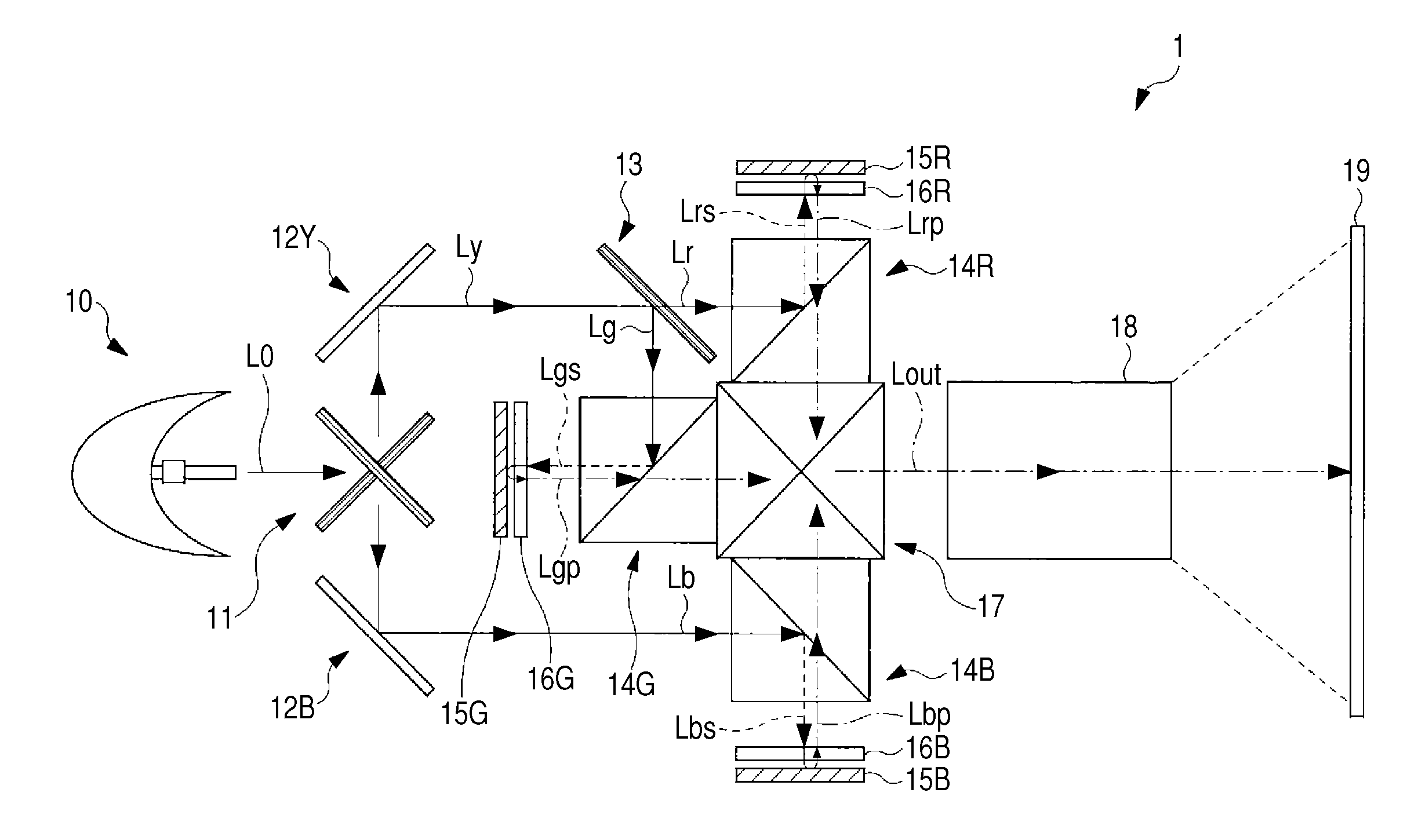
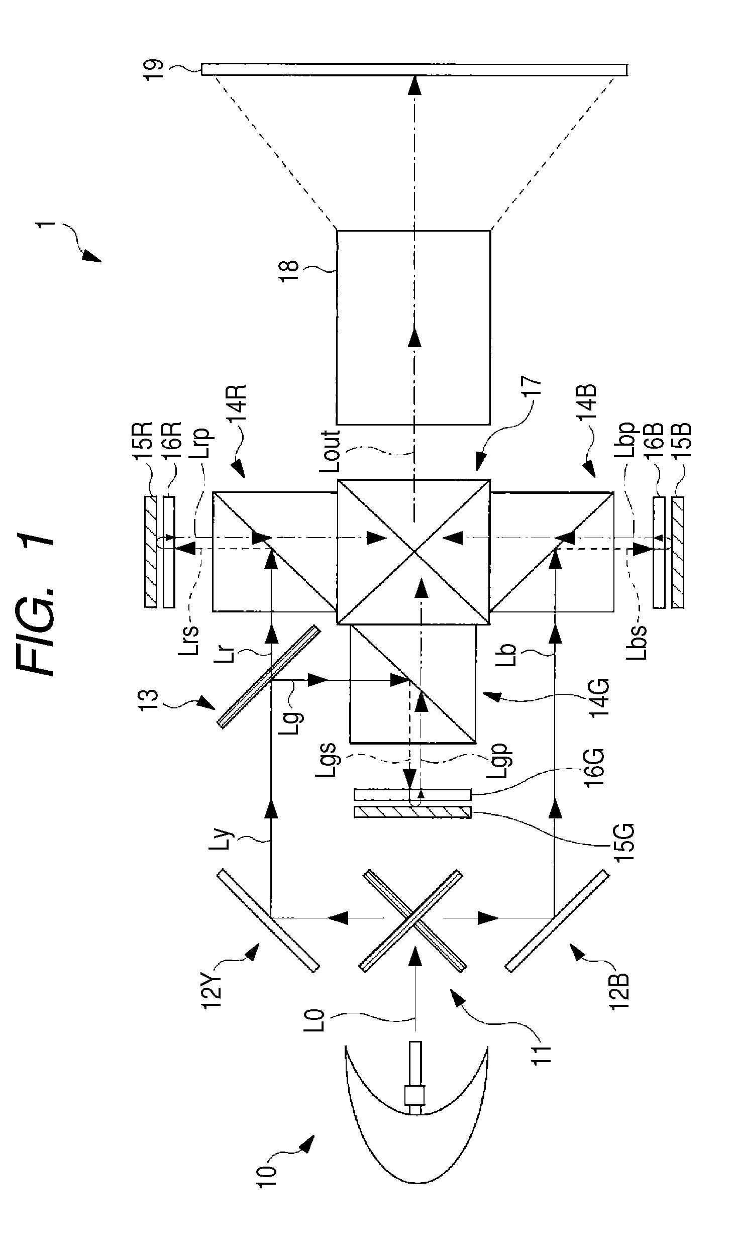
[0029]FIG. 1 shows a general configuration of a projection type liquid crystal display (liquid crystal projector) 1 according to an embodiment of the invention. The liquid crystal projector 1 displays an image based on an input image signal (not shown) supplied from outside. The liquid crystal projector 1 includes a light source unit 10, dichroic mirrors 11 and 13, reflecting mirrors 12B and 12Y, polarization beams splitters (PBSs) 14R, 14G, and 14B, reflective liquid crystal panels 15R, 15G, and 15B, compensation plates 16R, 16G, and 16B, a cross prism 17, and a projection lens 18.

[0030]The light source 10 emits white light (illumination light) L0 including light beams in primary colors, i.e., red light Lr, green light Lg, and blue light Lb which are necessary for color image display. For example, the light source may be a halogen lamp, metal halide lamp, or xenon lamp.

[0031]The dichro...


PUM

PropertyMeasurementUnit
refractive indicesaaaaaaaaaa

Abstract

A projection type liquid crystal display includes a light source, a reflective liquid crystal element modulating light from the light source based on an image signal, a polarization beam splitter disposed on an optical path between the light source and the liquid crystal element, a compensation plate disposed on an optical path between the liquid crystal element and the beam splitter, and projection means for projecting light impinging thereon through an optical path extending through the compensation plate and the beam splitter upon a screen, the light impinging upon the projection means after being modulated by the liquid crystal element. The compensation plate has in-plane retardation Re being one-fourth the wavelength of the incident light and retardation RthL in the thickness direction which is equal to retardation RthC in the thickness direction of the liquid crystal element in absolute value and is the reverse of the retardation RthC in polarity.

Description

CROSS REFERENCES TO RELATED APPLICATIONS[0001]The present invention contains subject matter related to Japanese Patent Application JP 2007-254167 filed in the Japanese Patent Office on Sep. 28, 2007, the entire contents of which being incorporated herein by reference.BACKGROUND OF THE INVENTION[0002]1. Field of the Invention[0003]The present invention relates to a projection type liquid crystal display including a reflective liquid crystal element and a polarization beam splitter and a compensation plate used in such a projection type liquid crystal display.[0004]2. Description of the Related Art[0005]Projection type liquid crystal displays (liquid crystal projectors) have come into wide use. In such displays, light incident on a liquid crystal element exits the element after being spatially modulated according to an electrical signal applied to the liquid crystal element, and the exiting light is collected and projected to display an image. In general, such a projection type liquid...

Claims


Application Information

Patent Timeline
Patent Type & Authority Applications(United States)
IPC IPC(8): G02F1/13363
CPCG03B21/2066G03B33/12G03B21/2073G02F1/1335G02F1/13363
Inventor KAIDA, HIROKAZUWATANABE, SHINYA
Owner SONY CORP
Why Eureka
Try Eureka