
Switch, switch assembly and switch seal structure

a technology of switch assembly and seal structure, which is applied in the direction of emergency protective devices, emergency actuators, transportation and packaging, etc., can solve the problems of degrading sealing properties of seal members in corners, not having waterproofing properties, etc., and achieves the effect of preventing degradation of sealing properties and improving sealing properties

Active Publication Date: 2015-12-10
YAMAHA MOTOR CO LTD
View PDF3 Cites 1 Cited by
  • Summary
  • Abstract
  • Description
  • Claims
  • Application Information

AI Technical Summary

Benefits of technology

The patent text is about a new type of switch that can be attached to an outboard motor and has better waterproofing properties. The switch has a simple construction and includes a seal holding portion that fits tightly to the attachment object, preventing any leaks. Additionally, the push operation is performed on a flange portion, which prevents any operating load from affecting the pawl portion and ensures that the switch does not detach. Overall, this new switch has improved sealing properties and is more durable and cost-effective than current options.

Problems solved by technology

JP-A-H03-118294 enables the switch to be easily attached to the operating handle, but does not have waterproofing properties.
In this type of seal structure, a seal member cannot fit to the corners of the rectangular flange in a good condition.
Thus, the sealing properties of the seal member degrade in the corners, and the seal structure cannot exert sufficient waterproofing properties.
However, the attachment structure including the bracket 102 thus having a large size includes a drawback of increase in cost, weight or layout space.

Method used


Image

  • Switch, switch assembly and switch seal structure
  • Switch, switch assembly and switch seal structure
  • Switch, switch assembly and switch seal structure

Examples


Embodiment Construction

[0038]Preferred embodiments of the present invention will be hereinafter explained with reference to the attached drawings.

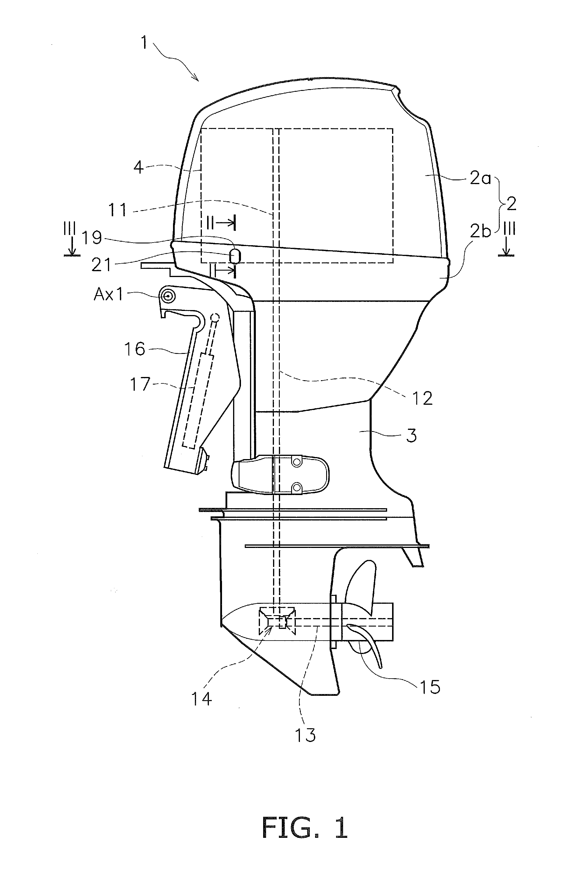
[0039]FIG. 1 is a side view of an outboard motor 1 according to a first preferred embodiment. The outboard motor 1 includes an engine cover 2, a casing 3 and an engine 4. The engine cover 2 accommodates the engine 4. The engine cover 2 includes an upper cover 2a and a lower cover 2b. The upper cover 2a is disposed over the lower cover 2b. The upper cover 2a is attached to the lower cover 2b. The casing 3 is disposed under the engine cover 2.

[0040]The engine 4 is disposed inside the engine cover 2. The engine 4 includes a crankshaft 11 extending in the up-and-down direction. A driveshaft 12 is disposed inside the casing 3 and extends in the up-and-down direction. The driveshaft 12 is coupled to the crankshaft 11.

[0041]A propeller shaft 13 is disposed in the lower portion of the casing 3. The propeller shaft 13 extends in the back-and-forth direction. The propelle...


PUM


Abstract

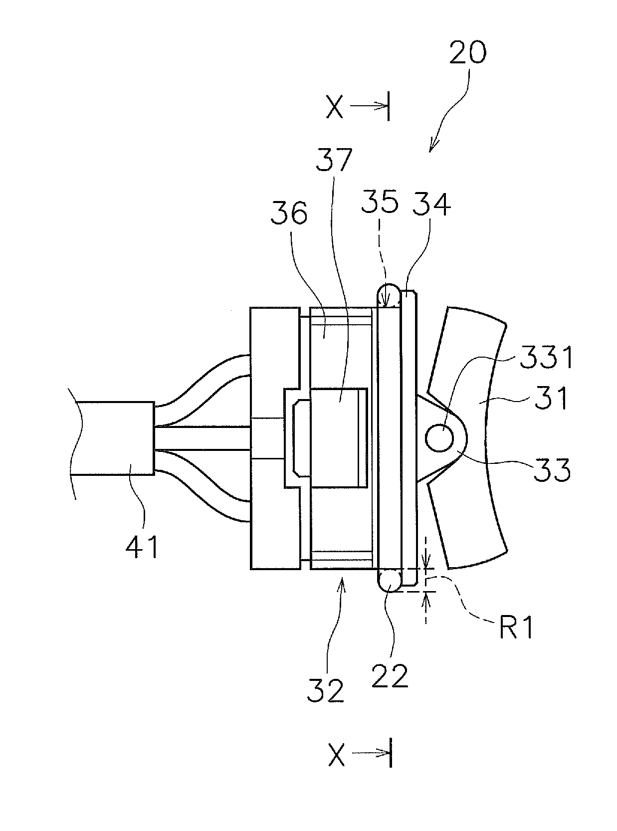
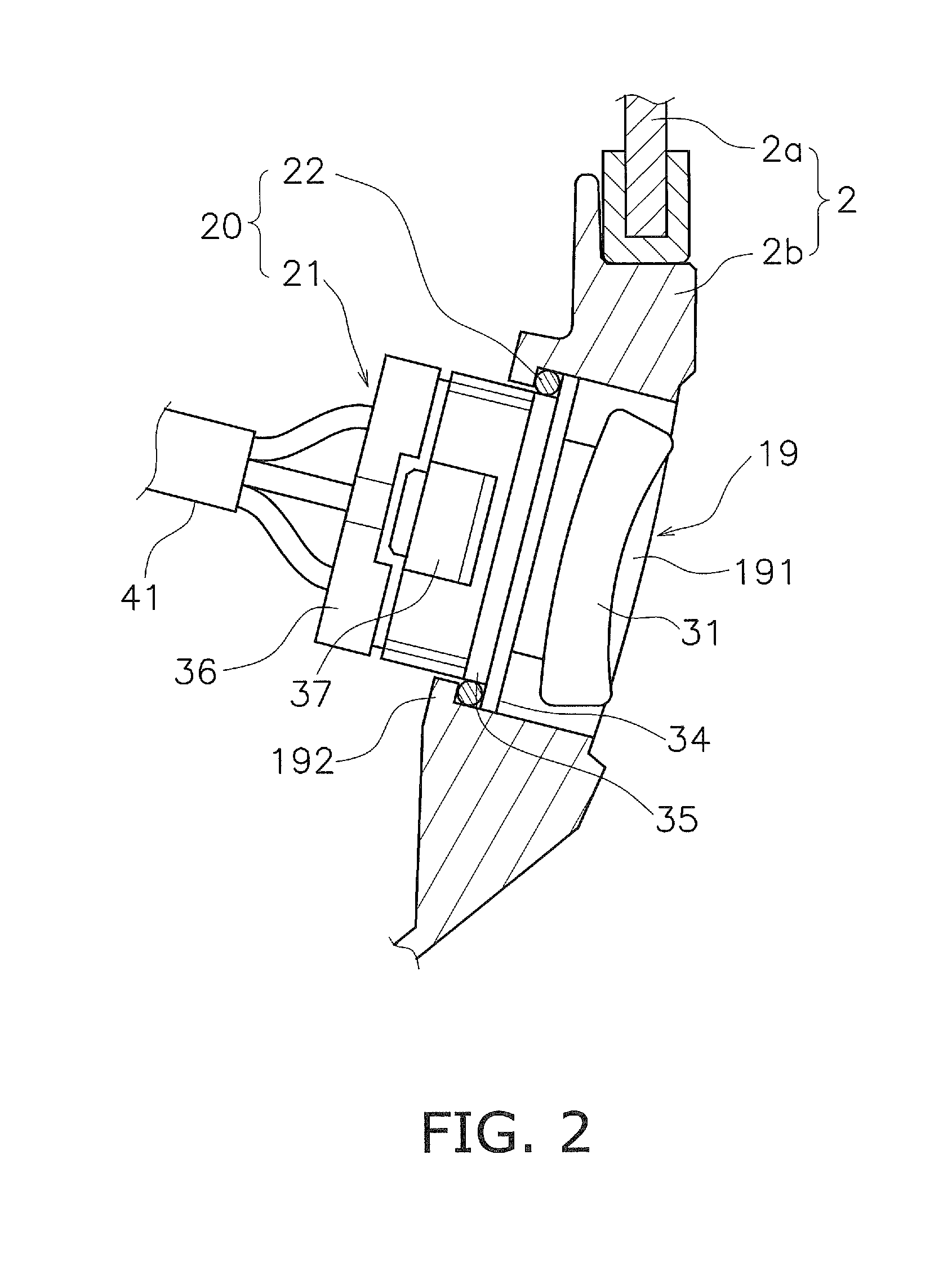
Provided is a switch attached to an attachment object through a seal member. The switch includes an operating portion including an operating surface. The switch further includes a support portion supporting the operating portion to enable a push operation for the operating portion. The switch further includes a flange portion disposed in a direction of the push operation relative to the support portion. The switch further includes a seal holding portion disposed in the direction of the push operation relative to the flange portion. The seal holding portion has a circular shaped portion or an oval shaped portion in contact with the seal member to hold the seal member with the circular shaped portion or the oval shaped portion. The switch further includes a pawl portion disposed in the direction of the push operation relative to the seal holding portion and configured to be hooked to the attachment object.

Description

CROSS-REFERENCE TO RELATED APPLICATIONS[0001]This application claims priority to Japanese Patent Application No. 2014-117921 filed on Jun. 6, 2014, the entirety of which is hereby incorporated by reference in its entirety.BACKGROUND OF THE INVENTION[0002]1. Field of the Invention[0003]The present invention relates to a switch, a switch assembly and a switch seal structure.[0004]2. Description of the Related Art[0005]A water vehicle is provided with various types of switches. For example, a PTT switch is configured to be operated for adjusting the tilt and trim angles of an outboard motor. The PTT switches are attached to a plurality of positions such as an outboard motor body, a tiller handle, a remote controller and so forth.[0006]When a given one of the switches is designed to be attached to a position with low necessity for waterproofing, attaching the switch to the position is performed with a simple construction as described in, for instance, Japan Laid-open Patent Application ...

Claims


Application Information

Patent Timeline
IPC IPC(8): H01H23/24H01H23/12H01H23/06
CPCH01H23/24H01H23/06H01H2221/016H01H2231/026H01H23/12
Inventor TAKEDA, YUKIO
Owner YAMAHA MOTOR CO LTD
Learn More