Method and an arrangement in condition monitoring of an elevator rope

a condition monitoring and elevator rope technology, applied in the direction of elevators, mine lifts, material resistance, etc., to achieve the effect of improving the safety of the elevator, simple, safe and efficient damage detection

Active Publication Date: 2015-12-17
KONE CORP
View PDF1 Cites 32 Cited by
  • Summary
  • Abstract
  • Description
  • Claims
  • Application Information

AI Technical Summary

Benefits of technology

[0007]Embodiments are presented which, inter alia, facilitate simple, safe and efficient damage detection of non-metallic, preferably carbon-fibre-reinforced polymer composite load bearing parts in said elevator ropes. Also, embodiments are presented, where invisible damages including mechanical damages during transportation, environmental effects that has caused extra stress or overload of the rope, specified temperature- and / or humidity levels exceeded during logistics chain, such as storing the rope under the sun, as well as mechanical damages during installation such as tight bending of punch or rope left in high compression are detected. Also, embodiments are presented, where reliable in situ condition monitoring of the ropes throughout the elevator life, even before the rope is installed into an elevator, is possible and safety of the elevator is improved.

Problems solved by technology

Also, embodiments are presented, where invisible damages including mechanical damages during transportation, environmental effects that has caused extra stress or overload of the rope, specified temperature- and / or humidity levels exceeded during logistics chain, such as storing the rope under the sun, as well as mechanical damages during installation such as tight bending of punch or rope left in high compression are detected.

Method used


Image

  • Method and an arrangement in condition monitoring of an elevator rope
  • Method and an arrangement in condition monitoring of an elevator rope
  • Method and an arrangement in condition monitoring of an elevator rope

Examples


Embodiment Construction

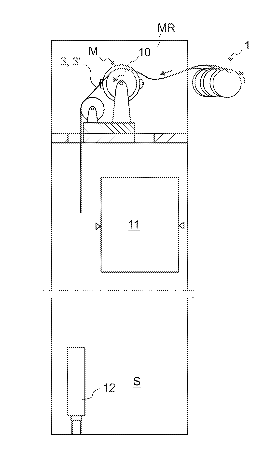
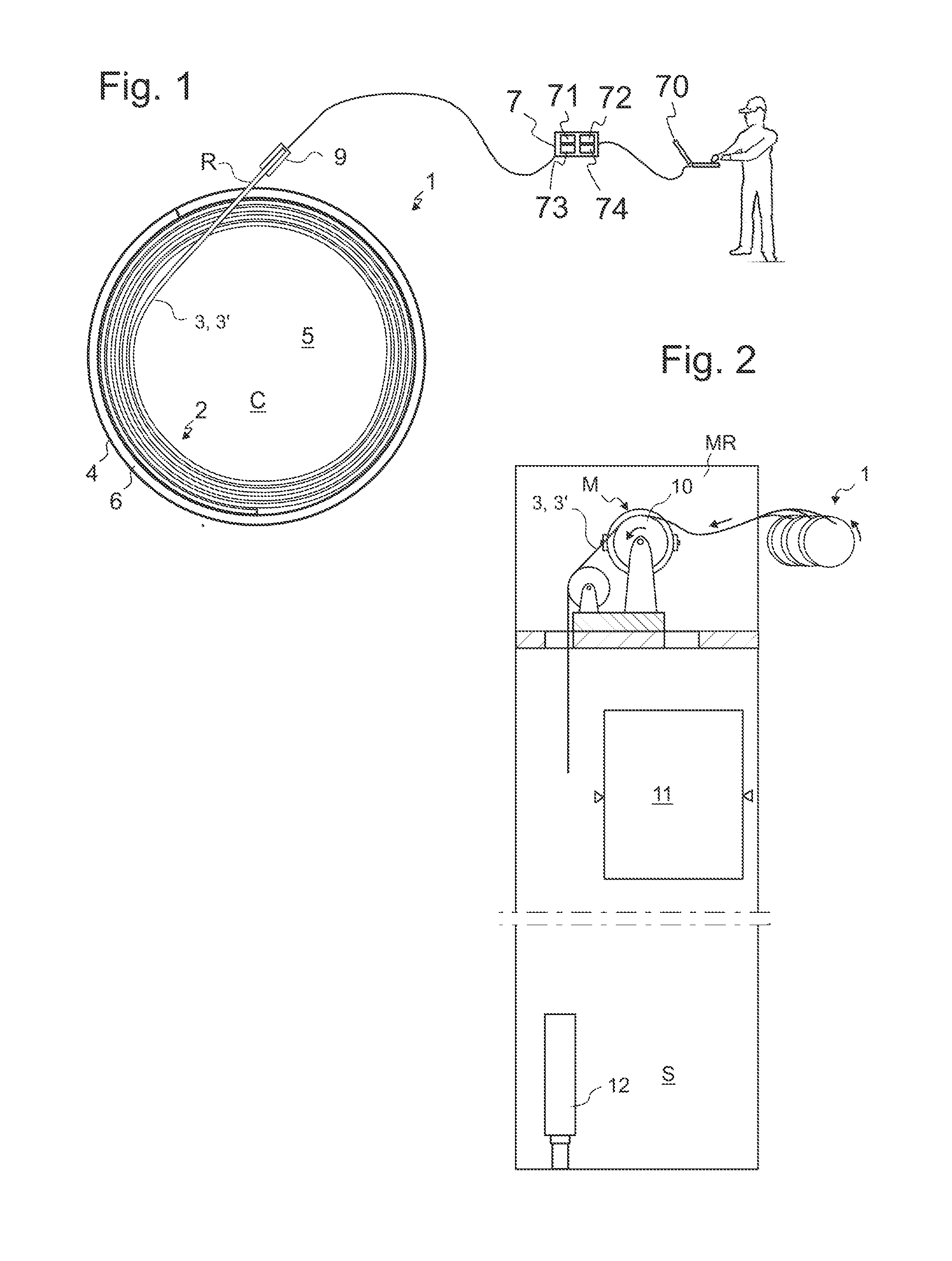
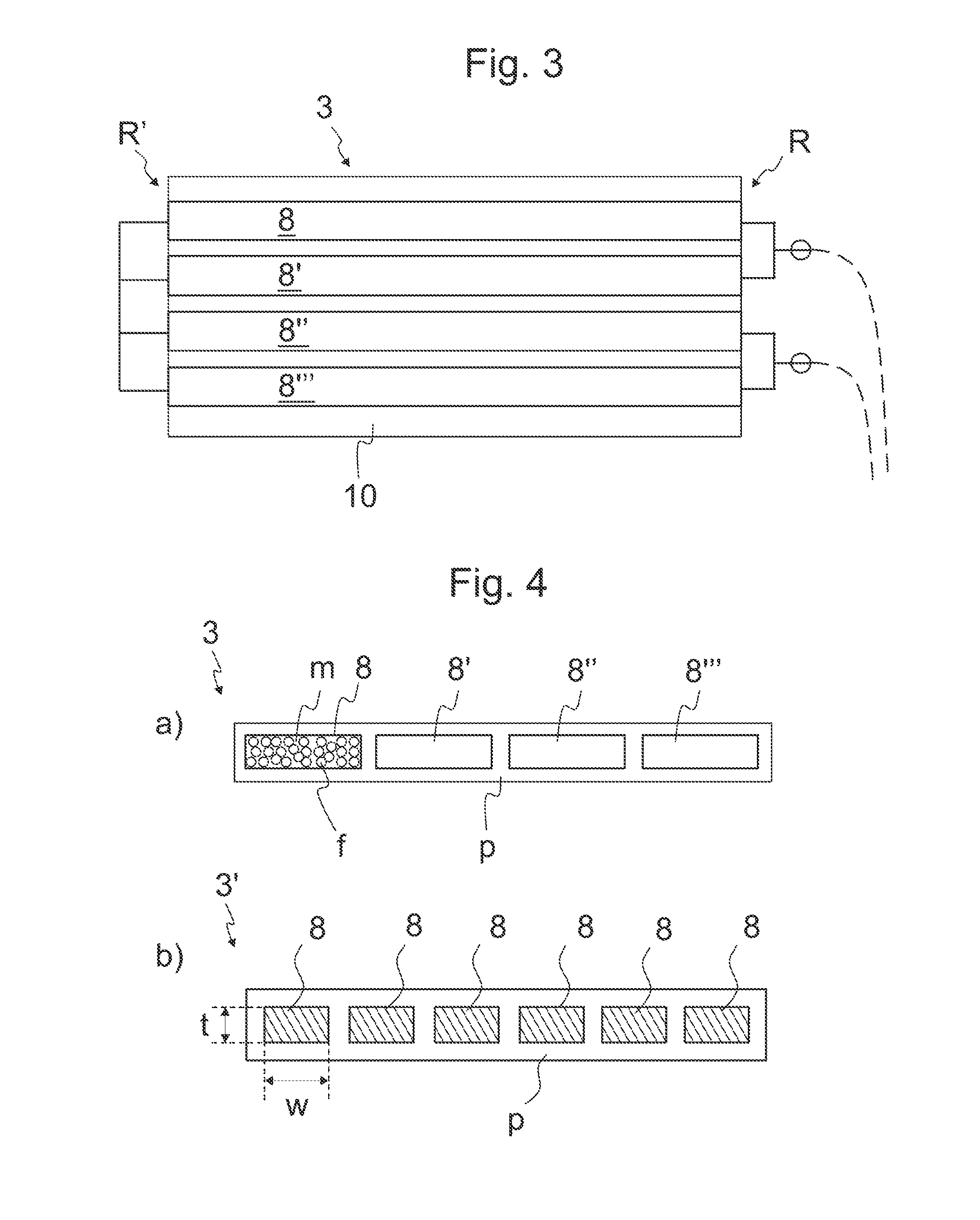
[0064]FIG. 1 illustrates overview of the arrangement in condition monitoring of an elevator rope where method steps of the invention can be performed. The rope storage unit 1 comprises a rope reel 2, formed by a rope 3, 3′ wound in a spiral form. The rope 3, 3′ has two ends, i.e. a first end and a second end. A rope end block 9 is attached on said end face side of the elevator rope first end. Electrical rope condition monitoring means 7 are connected to the rope 3, 3′ via said rope end block 9.

[0065]Preferably rope end block 9 is a single piece structure manufactured from plastics or some other electrically nonconductive material, such as from thermoplastics polymer or thermosetting polymer. Preferably rope end block 9 comprises a first frame portion attached to the elevator rope end with fastening means. It is thus possible for the fastening means to pass through the openings in the first frame portion of the rope end block 9. The fastening means can advantageously be made of metal...


PUM

PropertyMeasurementUnit
voltageaaaaaaaaaa
heightaaaaaaaaaa
heightaaaaaaaaaa

Abstract

The invention relates to a method in rope condition monitoring of an elevator, in which method at least the following steps are performed: elevator suspension and/or transmission ropes are reeled and packed on a rope storage unit, and thereafter electrical resistance between a first point and a second point of elevator suspension and/or transmission ropes is measured first time, and thereafter a threshold value is determined based on the measurement, and thereafter rope is delivered into an installation site, and thereafter electrical resistance between the first point and the second point of said suspension and/or transmission ropes is measured second time, and thereafter results of said second time measurement are compared with said threshold value, and if said second time measurement meets said threshold value, predetermined actions are carried out. The invention also relates to an arrangement in rope condition monitoring of an elevator.

Description

[0001]This application claims priority to Finnish Patent Application No. 20145568 filed on Jun. 17, 2014, the entire contents of which are incorporated herein by reference.FIELD OF THE INVENTION [0002]The invention relates to damage detection and condition monitoring of an elevator rope. The rope is, in particular, a rope for an elevator meant for transporting passengers and / or goods.BACKGROUND OF THE INVENTION[0003]Storing of an elevator rope may be needed in various stages of its lifetime. The storing is conventionally implemented by forming a rope reel of the rope so that it can be stored and / or transported as a compact unit. In the field of elevators, storing is usually needed for transporting the rope from production to the site, and further to the specific installation location where the rope can be unwound and installed in the elevator.[0004]There are a lot of potential places in logistics chain as well as during installation where rope can be damaged without having visual in...

Claims


Application Information

Patent Timeline
Patent Type & Authority Applications(United States)
IPC IPC(8): G01N27/20B66B5/00
CPCB66B5/00G01N27/20B66B7/1223B66B19/02
Inventor LEHTINEN, HANNUPURANEN, MIKKO
Owner KONE CORP
Why Eureka
Try Eureka