

Design method of LED freeform surface illumination system based on XY-polynomial
a freeform surface and design method technology, applied in the field of design methods of led freeform surface illumination systems based on xypolynomial, can solve problems such as corrupting the uniformity of illumination
- Summary
- Abstract
- Description
- Claims
- Application Information
AI Technical Summary
Benefits of technology
Problems solved by technology
Method used
Image


Examples
example 1
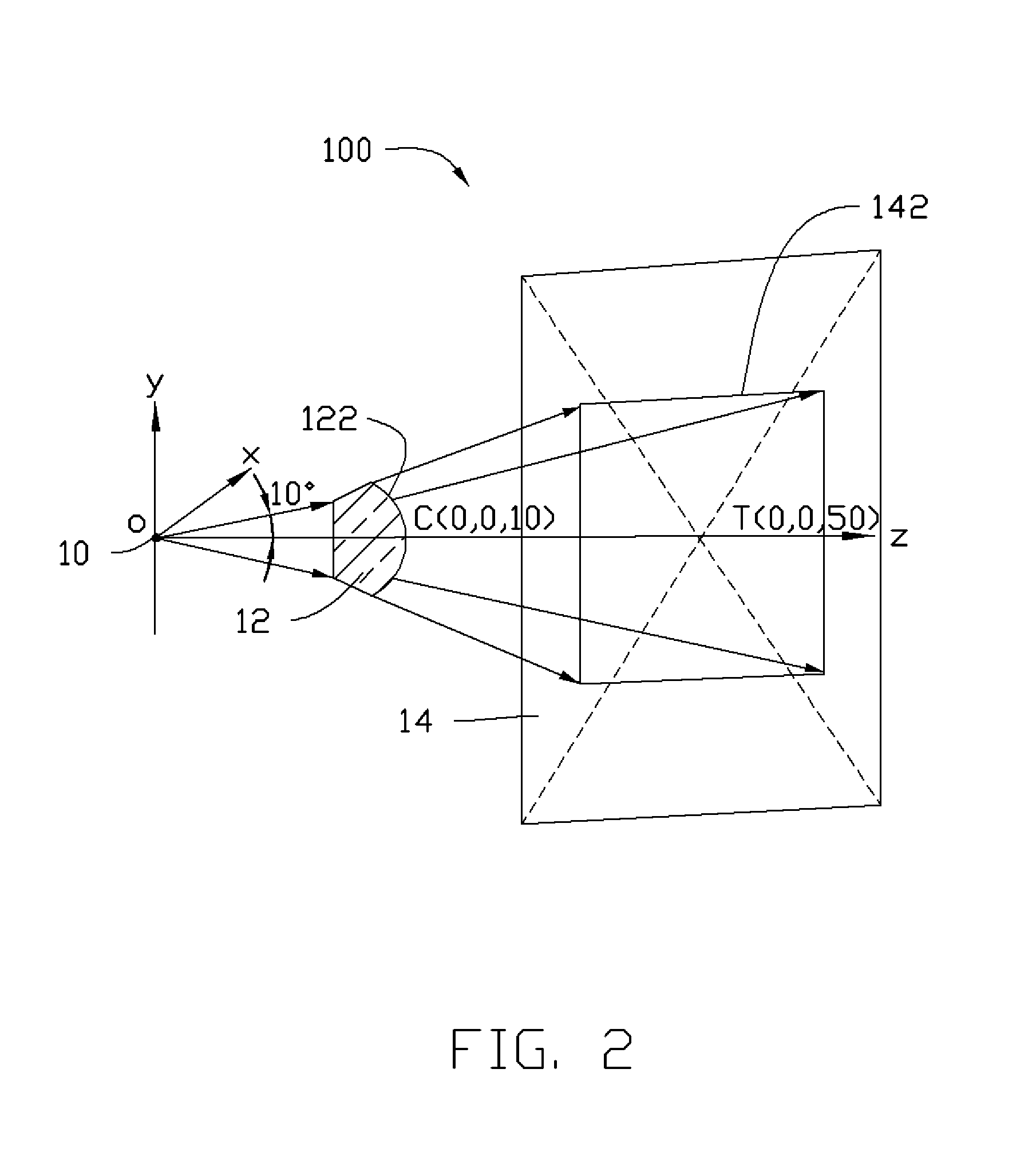
[0035]Referring to FIG. 2, an LED point light source 10 is taken as origin O and a three-dimensional Cartesian coordinate system Oxyz is constructed. A freeform surface 122 and z axis intersect at C=(0, 0, 10 mm). A cone beam is emitted from the LED point light source 10 and centered on the +z axis with one half of an angular aperture being 10°. The cone beam passes through the freeform surface 122 and forms a rectangular illuminated field 142 having a length of 30 mm and a width of 20 mm on a receiving surface 14. The receiving surface 14 is parallel to xy plane and intersects the z axis at T=(0, 0, 50 mm). Based on the above conditions, a plurality of data points of the freeform surface 122 are obtained through a differential equation method and further fitted with a fourth order XY-polynomial as a prototype, wherein the fourth order XY-polynomial can be expressed in terms of the following equation:
z=P0+P1x2+P2y2+P3x4+P4x2y2+P5y4
Coefficients of the fouth order XY-polynomial are o...
example 2
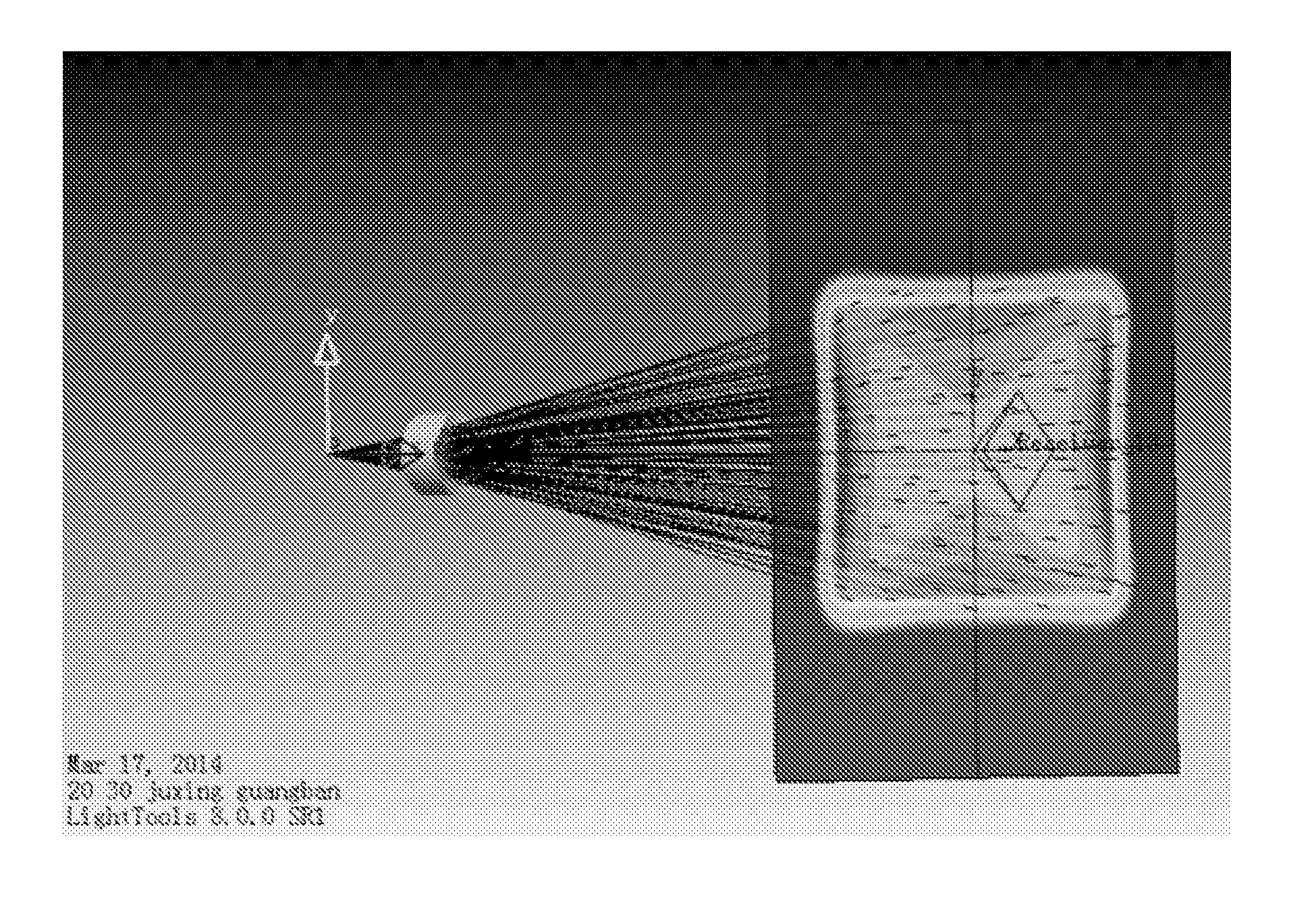
[0037]A design method of the second example is substantially the same as the design method of the first example, except that the cone beam forms a square illuminated field with its side as 20 mm. Coefficients of the fourth order XY-polynomial are obtained as follows: P0=10, P1=−0.0095, P2=−0.0095, P3=−0.0047, P4=0.0222, P5=−0.0047, wherein the weighting w is 10.
[0038]Referring to FIGS. 6˜8, FIG. 6 is a diagram showing a ray tracing simulation of a freeform surface constructed using LIGHTTOOLS version 8.0 SR1. FIG. 7 is an illuminating effect image of the square illuminated field formed through the freeform surface. FIG. 8 is a diagram showing illuminance distributions on x axis and y axis of the square illuminated field formed through the freeform surface. FIGS. 6˜8 illustrate that the illumination uniformity of the square illuminated field is almost complete, and the shape and size match the design requirement. The energy utilization efficiency of the LED freeform surface illuminat...
example 3
[0039]Referring to FIG. 9, the LED point light source 10 is taken as origin O and the three-dimensional Cartesian coordinate system Oxyz is constructed. A freeform surface 222 and the z axis intersect at C=(0, 0, 10 mm). The cone beam is emitted from the LED point light source 10 and is centered on the +z axis with the one half of the angular aperture being 10°. The cone beam passes through the freeform surface 222 and forms a circular illuminated field 144 of radius 10 mm on the receiving surface 14. The receiving surface 14 is parallel to xy plane and intersects the z axis at T=(0, 0, 50 mm). Based on the above conditions, a plurality of data points of the freeform surface 222 are obtained through differential equation method and further fitted with fourth order XY-polynomial as prototype, wherein the fourth order XY-polynomial can be expressed as the following equation:
z=P0+P1x2+P2y2+P3x4+P4x2y2+P5y4
Coefficients of the fourth order XY-polynomial are obtained as follows: P0=10, P...
PUM
 Abstract
Description
Claims
Application Information