Glove dispenser

a dispenser and glove technology, applied in the field of glove dispensers, can solve problems such as potential problems for glove wearers and patents

Inactive Publication Date: 2015-12-31
NEVAREZ SERGIO
View PDF34 Cites 42 Cited by
  • Summary
  • Abstract
  • Description
  • Claims
  • Application Information

AI Technical Summary

Benefits of technology

[0010]In another embodiment, a series of perforations may extend about the outer periphery of the glove, that secures

Problems solved by technology

This of course affects the sterility of the gloves which may contaminat

Method used


Image

  • Glove dispenser
  • Glove dispenser
  • Glove dispenser

Examples


Embodiment Construction

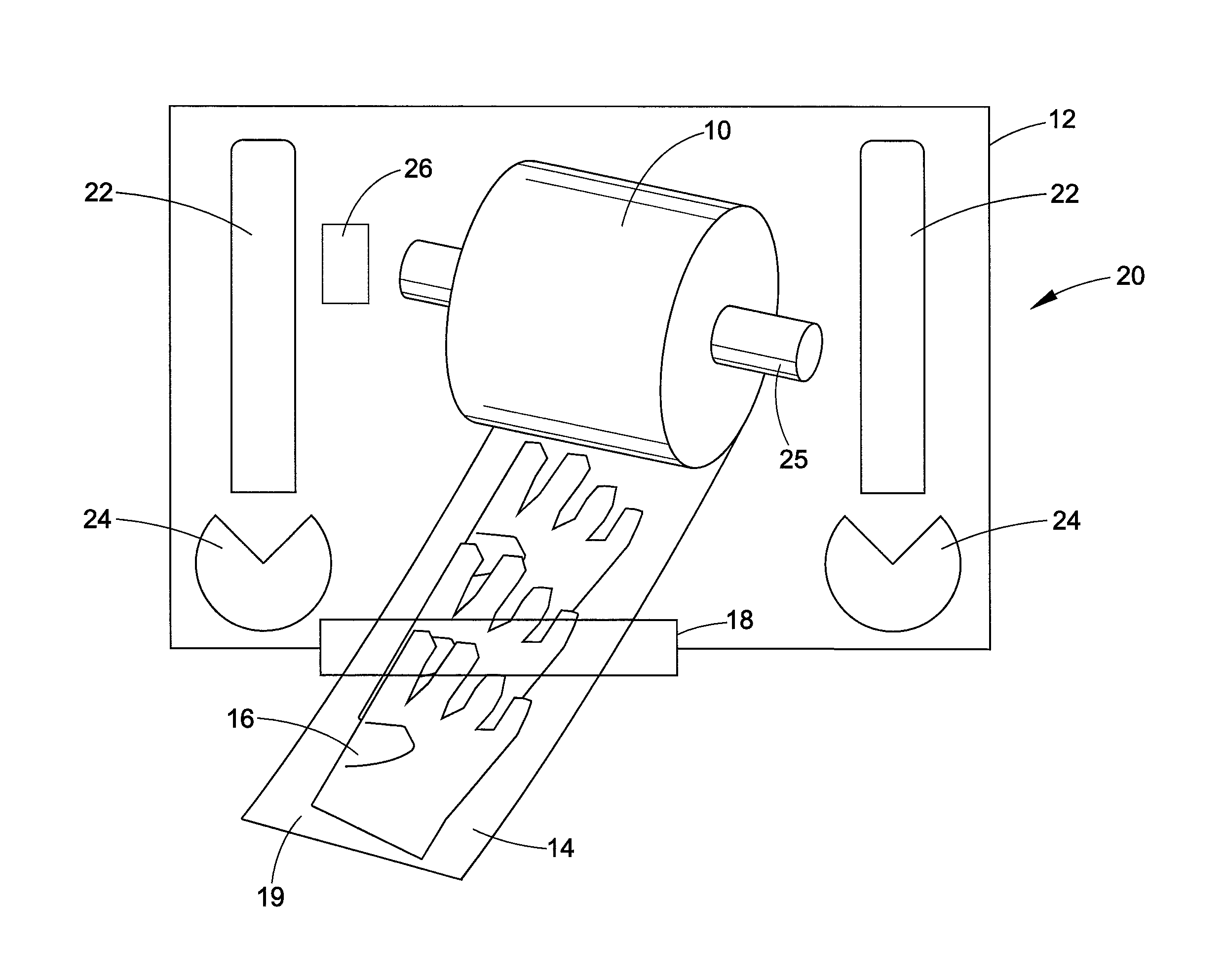
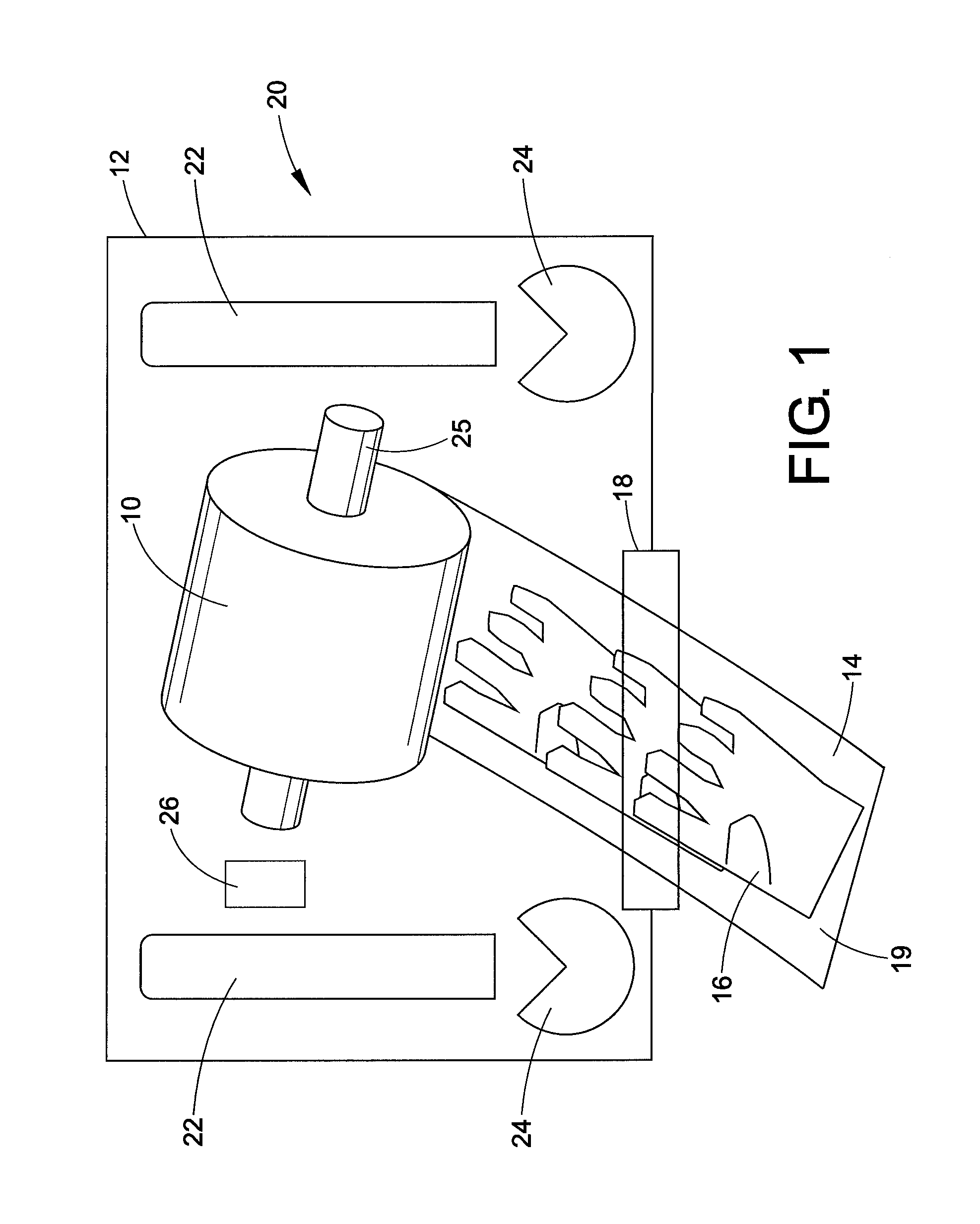
[0044]The disclosure relates to a glove dispenser. Specifically, it relates to an electro-mechanized glove dispenser for dispensing gloves for use in surgical, medical, or dental applications, but is not limited to those applications. The dispenser includes a housing of any appropriate shape or configuration.

[0045]Referring now to FIGS. 1-7, a glove dispenser mechanism in accordance with a preferred embodiment of the disclosure is shown. A roll 10 of material is disposed in a housing 12 for rotationally carrying a roll of removable gloves 16. The roll material itself can be made of various materials, such as silk, paper, a plastic film, etc. The gloves themselves can be mounted or placed on the roll of material, or can be removably secured thereto such as by adhesive material or Velcro®-like hook and loop fasteners or can be perforated on the material sheet itself. A dispensing slot 18 is defined and formed at a bottom of the housing through which the sheets of gloves are dispensed....


PUM


Abstract

A glove dispenser has a housing having first and second opposed walls. A glove roll is disposed within the housing for carrying a roll of removable gloves. An electro-mechanical feed mechanism rotates the roll. One or more proximity sensors are positioned within the housing to detect a user's hand and activate rotation of the glove roll. Activators are located on the housing first and second wall which activate the roll to rotate to dispense a glove from the roll. A take-up roll can be provided for receiving roll material after the gloves are dispensed.

Description

CLAIM OF PRIORITY[0001]This application claims priority from Provisional Application Ser. No. 62 / 018,055, filed on Jun. 27, 2014, the entirety of which is hereby incorporated by reference.BACKGROUND OF THE DISCLOSURE[0002]The disclosure relates to a glove dispenser. Specifically, it relates to an electro-mechanized glove dispenser for dispensing gloves for use in surgical, medical, or dental applications, but is not limited to those applications.[0003]Individuals in the health care or dental industry regularly don disposable gloves in order to prevent the transmission of bacteria or other contaminants to themselves and to patients. In certain cases, the disposable gloves are typically contained within, and dispensed from, a box or container. When donning a pair of gloves dispensed in this manner, a user typically grasps a glove and pulls the glove from the box using an uncovered hand. Once removed from the box, the user places the glove onto one of his uncovered hands. The user can ...

Claims


Application Information

Patent Timeline
IPC IPC(8): A61B19/04
CPCA61B50/20A61B42/40A61B2050/105A61B2017/00734A61B2017/00398
Inventor MACHADO, CAMILORAMIREZ, JAVIERMEDINA, CUTBERTONEVAREZ, SERGIO
Owner NEVAREZ SERGIO
Why Eureka
Try Eureka