Self-locking connector pin for demountably securing consumable ground digging components to containers of earth moving equipment

a technology of consumable ground digging components and connector pins, which is applied in the field of self-locking connector pins, can solve the problems of frequent replacement, high labor intensity, and high cost of replacing shrouds in accordance with the prior art, and achieves the effect of rapid and efficient installation and removal of shrouds

Active Publication Date: 2015-12-31
BIERWITH ROBERT S
View PDF17 Cites 7 Cited by
  • Summary
  • Abstract
  • Description
  • Claims
  • Application Information

AI Technical Summary

Benefits of technology

[0004]The present invention is directed to the manner in which the shrouds are secured to the lips of buckets, and replaced when worn or damaged, and concerns both a method and apparatus for rapidly and efficiently installing and removing shrouds from the lips.

Problems solved by technology

The shrouds and their connections to the lips of the buckets are subject to the most wear and tear of the entire bucket because they are exposed to constant abrasion, shaking, impacts and the like encountered during ground moving operations.
As a result, they require frequent replacement.
Replacing shrouds in accordance with the prior art is relatively time-consuming and labor intensive because it typically requires a combination of wedges and clamp like structures which must be manually hammered into place or out of their locked positions.
The excavating equipment must sit idle during that time, all of which is undesirable because it reduces profits.

Method used


Image

  • Self-locking connector pin for demountably securing consumable ground digging components to containers of earth moving equipment
  • Self-locking connector pin for demountably securing consumable ground digging components to containers of earth moving equipment
  • Self-locking connector pin for demountably securing consumable ground digging components to containers of earth moving equipment

Examples


Embodiment Construction

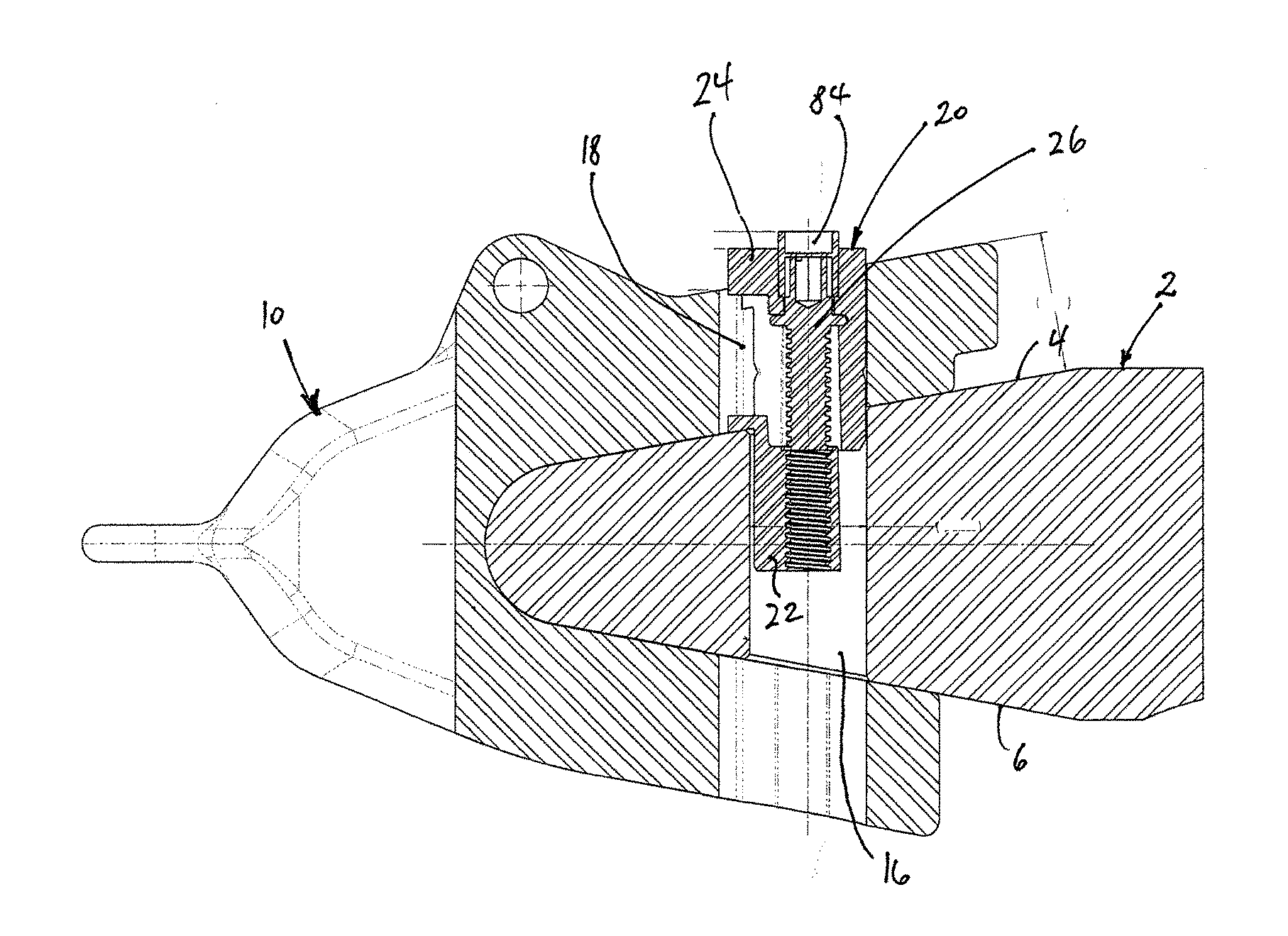
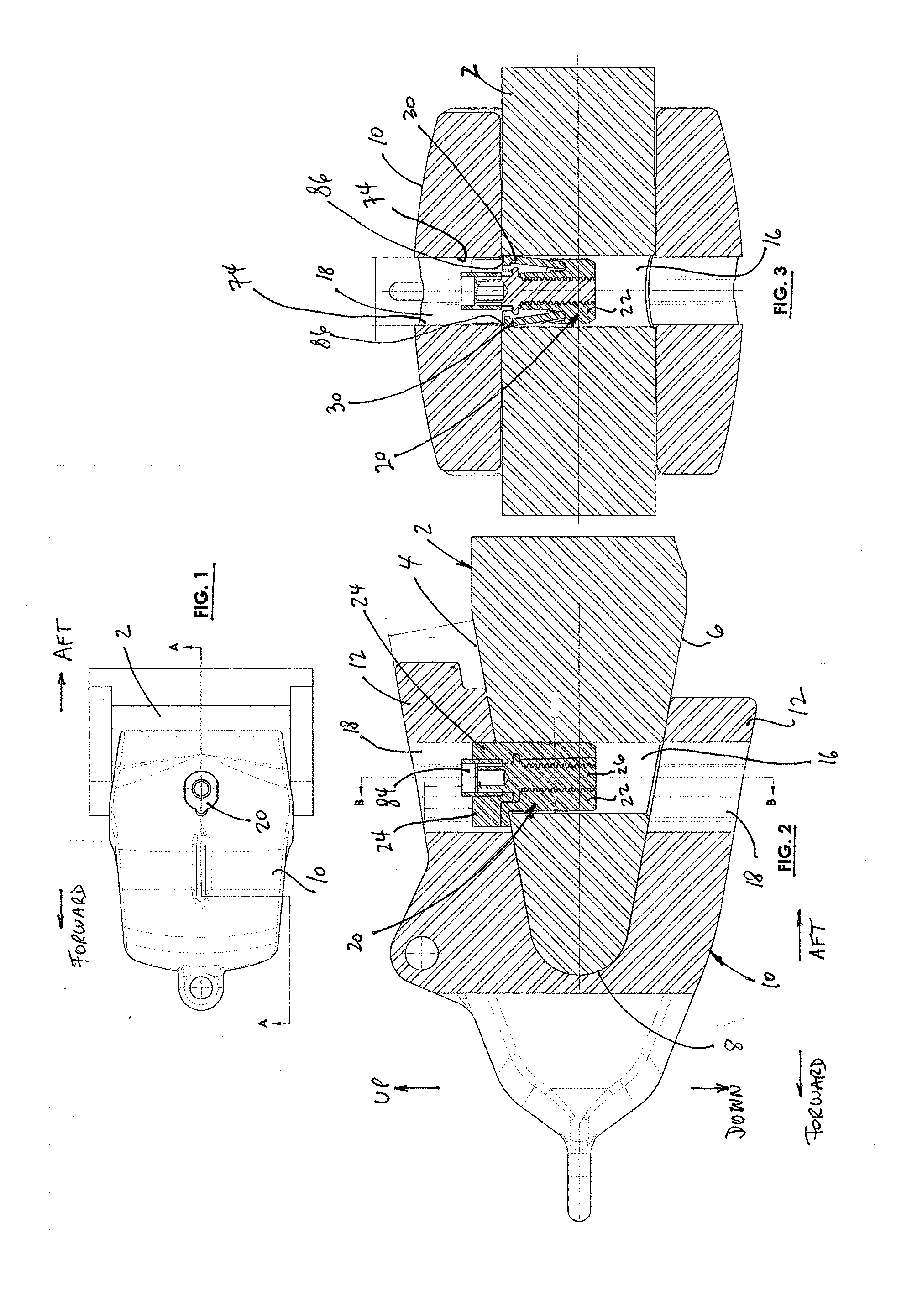
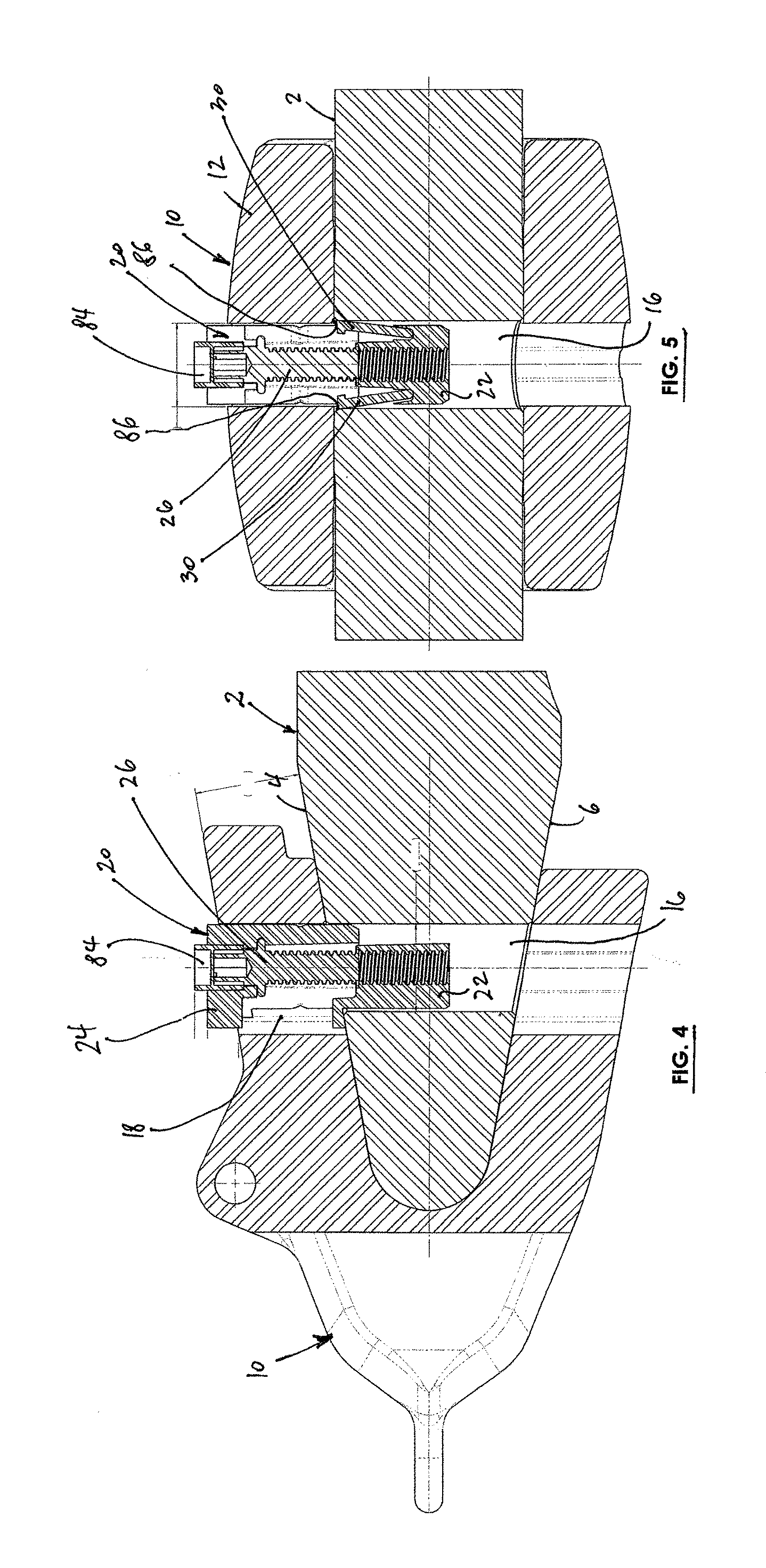
[0028]Referring to FIGS. 1-6, a lip 2 of a bucket (not separately shown) of earthmoving equipment (not separately shown) has forwardly converging upper and lower surfaces 4, 6 that terminate at a forward end 8 of the lip 2. A shroud 10 (as mentioned the term also encompasses consumable components such as adapters for teeth, teeth alone and other attachment demountably secured to the lip) has rearwardly diverging legs 12 that overly and engage the lip surfaces 4, 6.

[0029]The terms “forward”, “aft”, “up” and “down” as used herein to simplify the description and they refer to the typically horizontal orientation of the lip during installation and removal of the shroud and connector pin.

[0030]The lip 2 has a cylindrical hole 16 that communicates with an enlarged, oblong bore 18 in at least one of the legs of the shroud 10. The hole 16 and bore 18 are vertically oriented and to secure the shroud 10 to the lip 2 all that is required that the connector pin of this invention be manually dro...


PUM

PropertyMeasurementUnit
sizeaaaaaaaaaa
diameteraaaaaaaaaa
depthaaaaaaaaaa

Abstract

A method and apparatus for installing and removing shrouds from the lips of an earth moving bucket. The lips have forwardly converging upper and lower surfaces which are engaged by correspondingly rearwardly diverging legs of the shrouds that overly and are in contact with the lip surfaces. A hole is provided in the lip and an oblong hole in one of the legs that is aligned with the hole and has axially extending, spaced-apart flat walls which define engagement ledges that face and overlap the bore. A connector for securing the shroud to the lip is placed in the bore and the hole and has shaped exterior surfaces for positioning between the walls so that the connector is axially movable along the walls and past the engagement ledges while relative rotations between the connector and the hole in the leg are prevented.

Description

CROSS-REFERENCES TO RELATED APPLICATIONS[0001]This application claims the benefit of U.S. Provisional Application No. 62 / 018,502, filed on Jun. 27, 2014, which is incorporated by reference herein.BACKGROUND OF THE INVENTION[0002]Ground-moving, breaking and excavating equipment employs buckets, dragline buckets, shovels and other containers (hereafter collectively “buckets”) with which earth, gravel, rock formation and the like are excavated and moved around. Typically, such buckets carry a lip defining their digging edges, and the lips in turn mount consumable components which need periodic replacement, such as shrouds, adapters for digging teeth, digging teeth themselves and the like (hereinafter collectively “shrouds”).[0003]The shrouds and their connections to the lips of the buckets are subject to the most wear and tear of the entire bucket because they are exposed to constant abrasion, shaking, impacts and the like encountered during ground moving operations. As a result, they ...

Claims


Application Information

Patent Timeline
Patent Type & Authority Applications(United States)
IPC IPC(8): E02F9/28
CPCE02F9/2891E02F9/2841
Inventor BIERWITH, ROBERT S.
Owner BIERWITH ROBERT S
Why Eureka
Try Eureka