Tamper resistant receptacle

a technology of electrical receptacles and tamper-resistant receptacles, which is applied in the direction of live contact access prevention, coupling device connection, electrical apparatus, etc., can solve the problems of increased force, increased difficulty in movement, and excessive difficulty in insertion of plugs, etc., and achieve the effect of prolonging service li

Active Publication Date: 2015-12-31
HUBBELL INC
View PDF78 Cites 13 Cited by
  • Summary
  • Abstract
  • Description
  • Claims
  • Application Information

AI Technical Summary

Benefits of technology

[0013]Various embodiments of the present invention overcome various of the aforementioned and other disadvantages associated with prior art TR receptacles and offers new advantages as well. Although not wishing to be bound by theory, the present inventors' recognize that limiting the areas of contact between the sliding shutter members and / or the shutter housing results in a more frictionally advantageous configuration that may extend the service life of some prior art TR receptacles.

Problems solved by technology

Sliding two or more materials against each other results in increased force needed to compensate for the frictional forces attendant to the areas of contact.
Another presently appreciated issue recognized by the present inventors stems from the sharpness of plug blades being found on electrical products imported from overseas.
Over time, these sharp blades having a single point of initial contact begin to deform and cut into the ramp surface which makes movement more difficult as the blades get stuck in divets or scratches at the point of contact.
At some point, the deformity of the ramp surface may make insertion of a plug excessively difficult or even impossible.
At this point, the device has reached the end of its useful life.
Yet another presently appreciated issue recognized by the present inventors is that many convention TR receptacle designs cannot accommodate deployment in a 20 A receptacle due to the inability to provide sufficient clearance for the perpendicularly oriented neutral blade of the plug.
Furthermore, the foregoing highlights the long-felt, yet unresolved need in the art for a TR receptacle that may extend the useful life of the device.
Moreover, the forgoing highlights the long-felt, yet unresolved need in the art for a TR receptacle that has an extended service life at a reasonable cost.

Method used


Image

  • Tamper resistant receptacle
  • Tamper resistant receptacle
  • Tamper resistant receptacle

Examples


Embodiment Construction

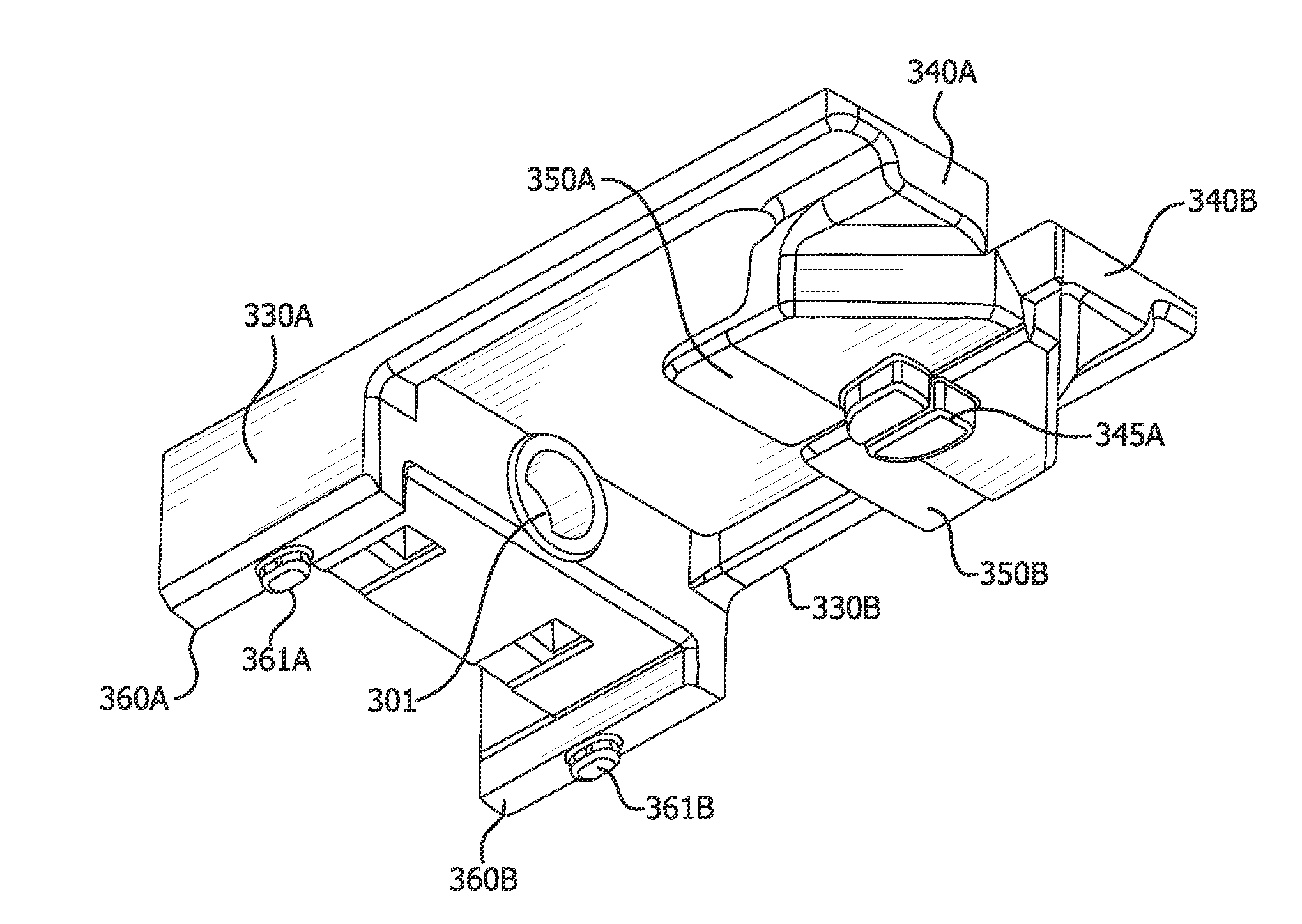
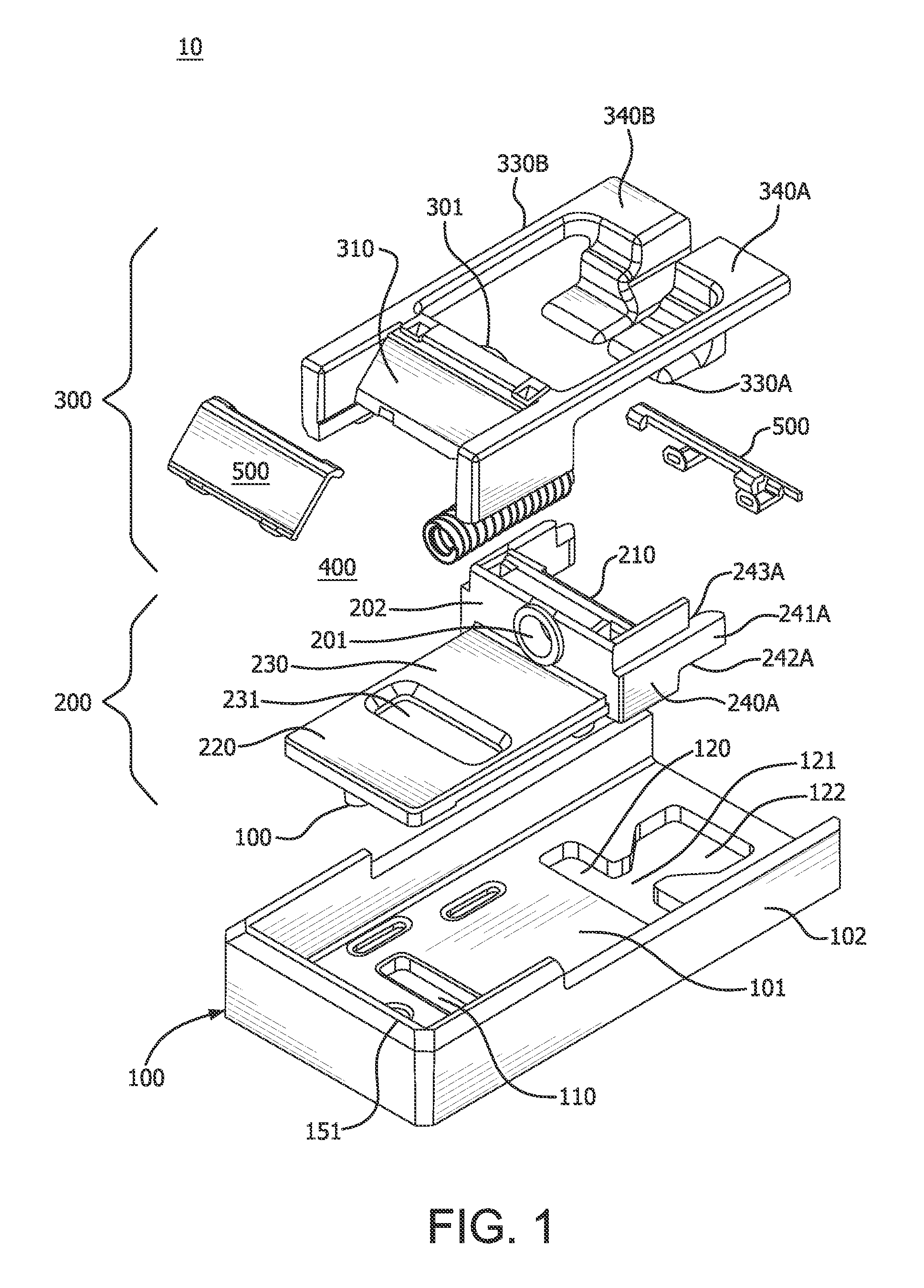
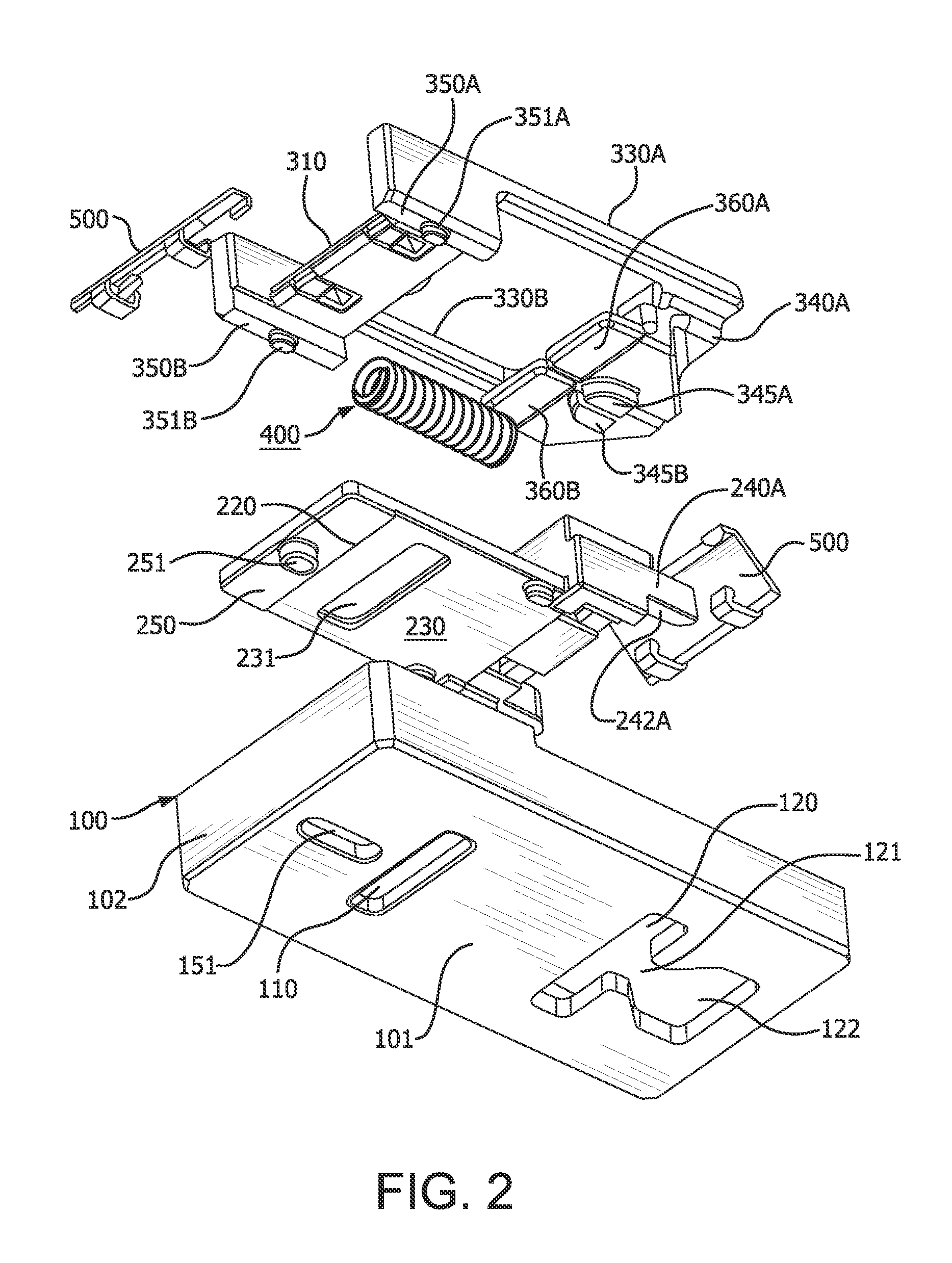
[0027]While the present invention will be described in connection with a TR receptacle of the type having cooperating shutters generally described above, it will be readily apparent to one of ordinary skill in the art armed with the present specification that the present invention can be applied to a multiplicity of fields and uses. In particular, the present invention may find use in connection with other types of TR receptacles where reduction in frictional contact between surfaces is desirable. One of ordinary skill in the art armed with the present specification will also understand that the present system may be easily modified to include different configurations, mechanisms, methods, and kits, which achieve some or all of the purposes of the present invention.

[0028]As will be discussed in more detail below, the basic concept described in an illustrative embodiment according to the present invention is that the hot slider does not make contact with the neutral slider. Rather, e...


PUM


Abstract

A tamper resistant electrical receptacle comprising a slide housing disposed beneath the hot and neutral blade openings in the receptacle. The slide housing includes a neutral slide body and a hot slide body having slide pads and tabs for reducing friction when the bodies slide against each other as the spring bias of the bodies in the slide housing is overcome by simultaneous insertion of the tines of an electrical plug contact ramp surfaces and camming past the slide bodies causing them to slide against each other and spreading a gap area a distance sufficient for receiving the lateral neutral prong of a 20 A electrical plug.

Description

CROSS-REFERENCE TO RELATED APPLICATIONS[0001]The present application claims the benefit of priority under 35 U.S.C. 102(e) from U.S. Provisional Application 62 / 015,131, filed Jun. 20, 2014, the contents of which are hereby incorporated by reference in their entirety.FIELD OF THE INVENTION[0002]The present invention relates to tamper resistant electrical receptacles. More particularly, the present invention relates to tamper resistant electrical receptacles using laterally sliding shutters spring biased to block access to the device's electrical contacts.BACKGROUND OF THE INVENTION[0003]Tamper resistant receptacles are known in the art. “Tamper Resistant” or “TR” receptacles are a class of electrical receptacle outlets configured to deny access to the device's electrical contacts unless force is applied simultaneously to both the hot and neutral plug openings of the device pursuant to NEC Code 406.11 et seq. The Code and related regulatory requirements provide that not only must the ...

Claims


Application Information

Patent Timeline
Patent Type & Authority Applications(United States)
IPC IPC(8): H01R13/453
CPCH01R13/4534
Inventor MORTUN, SORINDIAKOMIS, ATHANASIOS
Owner HUBBELL INC
Why Eureka
Try Eureka