Devices and methods for vaporization

a technology of vaporization device and vaporization chamber, which is applied in the direction of heating type, lighting and heating apparatus, and separation process, etc., can solve the problems of inefficient and/or inconsistent vapor formation, unsatisfactory user experience,

Inactive Publication Date: 2016-01-07
NJOY LLC
View PDF6 Cites 72 Cited by
  • Summary
  • Abstract
  • Description
  • Claims
  • Application Information

AI Technical Summary

Benefits of technology

[0004]The present disclosure includes a device comprising a vaporization unit, wherein the vaporization unit includes: a conduit; a heating element adjacent to an inner surface of the conduit; and a reservoir comprising a liquid; wherein the conduit allows passage of the liquid therethrough for vaporization by heat supplied by the heating element. Embodiments of the present disclosure may include one or more of the following features: the heating element may comprise a coil; the coil may extend an entire length of the conduit; the coil may have a curved configuration along the inner surface of the conduit; the conduit may be within a lumen of the reservoir, and the conduit and the reservoir may be coaxial; the conduit may be permeable; the conduit may comprise a heat-resistant material; a portion of the heating element may extend between the conduit and the reservoir; the device may further comprise a mesh within the conduit, wherein at least a portion of the heating element may be disposed between the conduit and the mesh; the mesh may comprise a metal or a metal alloy; the mesh may comprise a laminate; the reservoir may comprise an absorbent material saturated with the liquid; and/or the device may comprise an electronic cigarette.
[0005]The present disclosure further includes a device comprising: a vaporization unit, wherein the vaporization unit includes: a conduit; a heating coil adjacent to an inner surface of the conduit; and a reservoir surrounding at least a portion of the conduit, the reservoir comprising a liquid; and a b

Problems solved by technology

Yet, current devices may provide inefficient and/or inconsistent heating, which may lead to inefficient and/

Method used


Image

  • Devices and methods for vaporization
  • Devices and methods for vaporization
  • Devices and methods for vaporization

Examples


Embodiment Construction

[0013]Particular aspects of the present disclosure are described in greater detail below. The terms and definitions as used and clarified herein are intended to represent the meaning within the present disclosure. The patent literature referred to herein is hereby incorporated by reference. The terms and definitions provided herein control, if in conflict with terms and / or definitions incorporated by reference.

[0014]The singular forms “a,”“an,” and “the” include plural reference unless the context dictates otherwise.

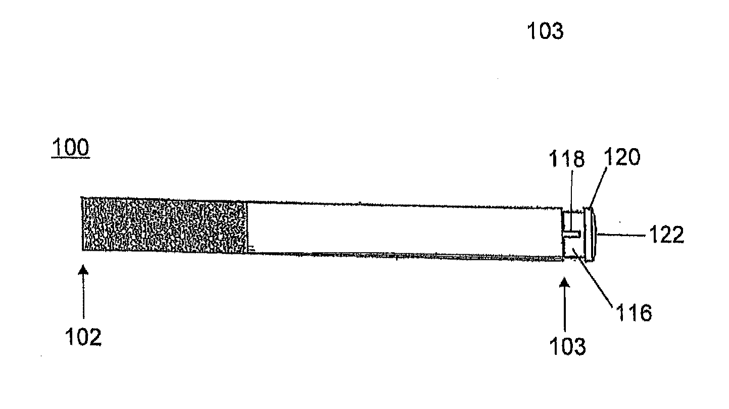
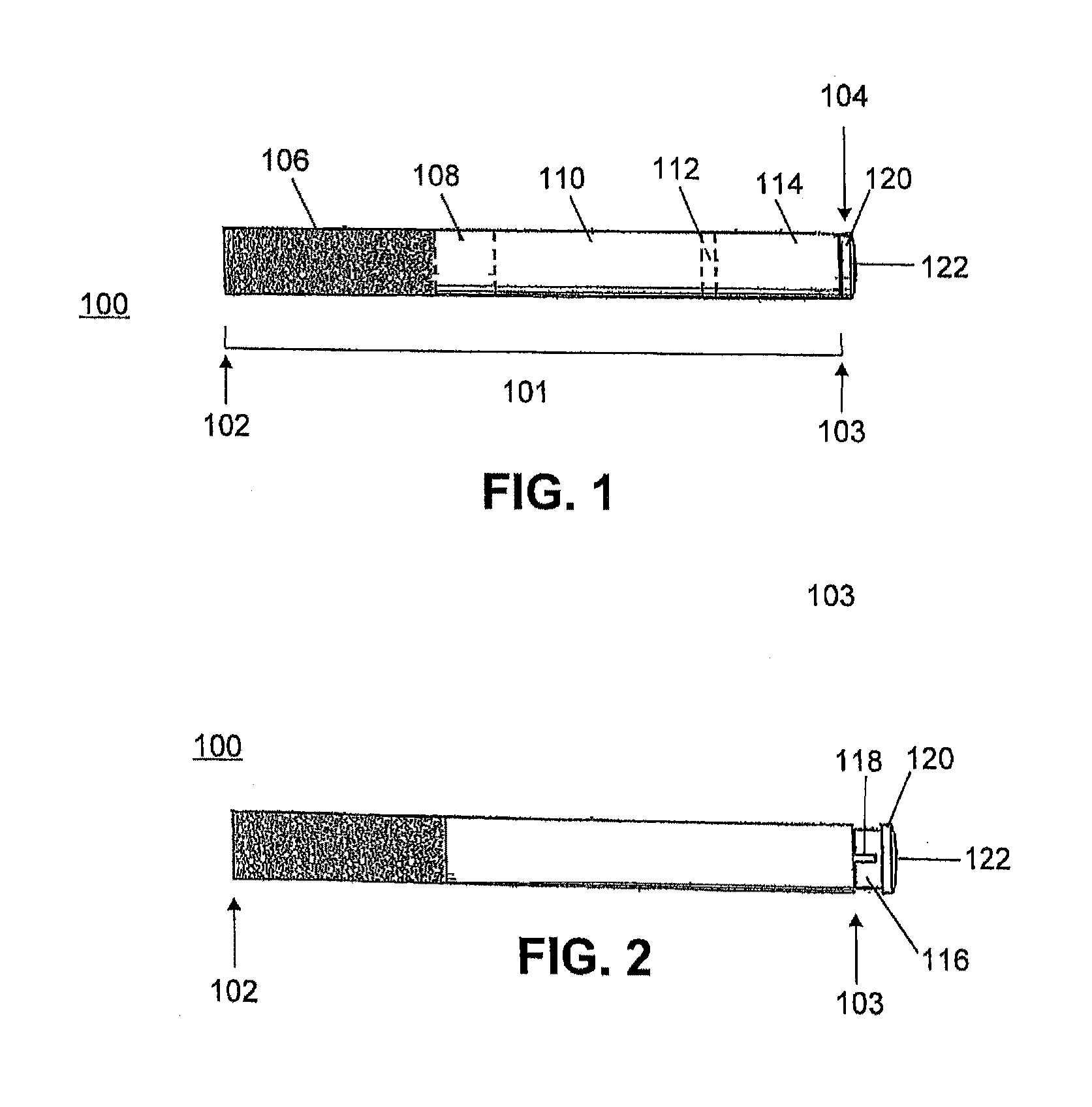
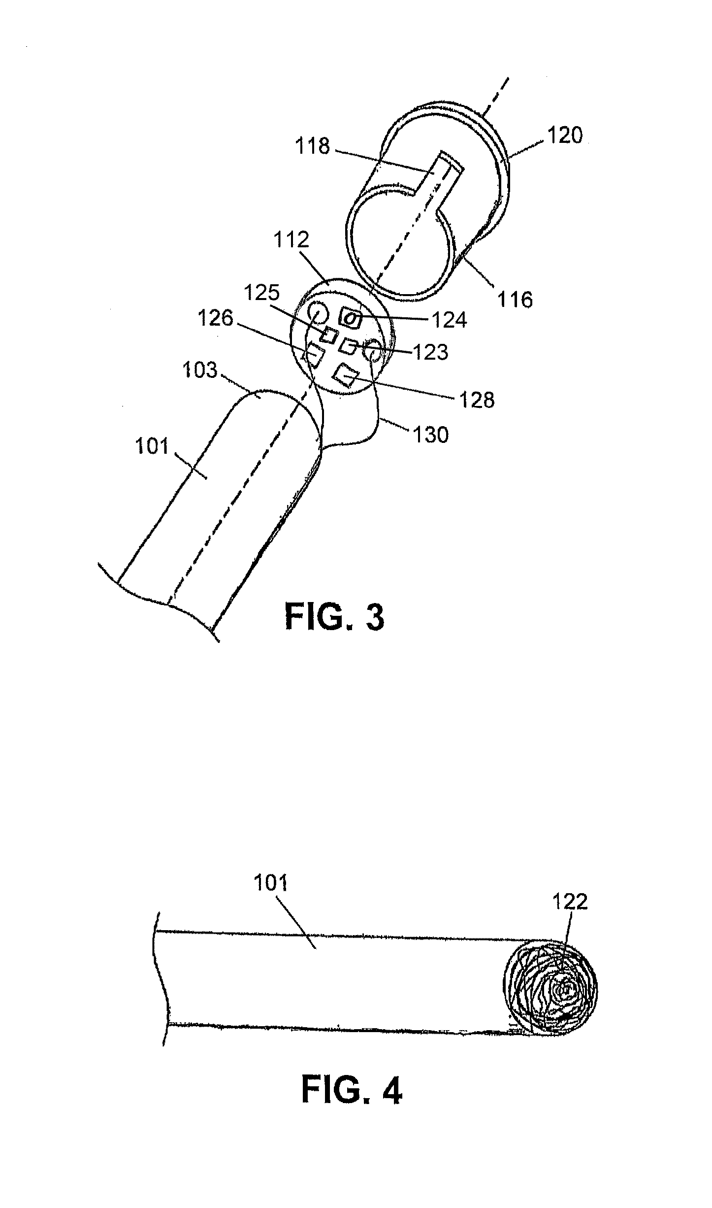
[0015]Embodiments of the present disclosure may include a vaporizing device such as an electronic cigarette comprising a vaporization unit and a power source (e.g., a battery), wherein the vaporization unit includes a conduit and a heating element coupled to an inside surface of the conduit.

[0016]Various aspects of the present disclosure may be used with and / or include one or more of the features or configurations disclosed in U.S. application Ser. No. 13 / 729,396, filed ...


PUM


Abstract

The present disclosure generally relates to vaporizing devices, e.g., electronic cigarettes. The vaporizing device may comprise a vaporization unit that includes a reservoir, a conduit, and a heating element coupled to an inside surface of the conduit. The conduit may be at least partially permeable or porous to allow passage of a liquid from the reservoir through the conduit for vaporization by heat supplied by the heating element. The heating element may be configured into a plurality of bends coupled to the inner surface of the conduit, and may be coupled to a metallic screen or mesh to secure the heating element to the conduit.

Description

CROSS-REFERENCE TO RELATED APPLICATION[0001]This application claims the benefit of priority from U.S. Provisional Application No. 62 / 020,068, filed on Jul. 2, 2014, which is incorporated by reference herein in its entirety.TECHNICAL FIELD[0002]The present disclosure generally relates to vaporizing devices and methods of use thereof, e.g., to generate aerosols for inhalation.BACKGROUND[0003]Electronic cigarettes, electronic cigars, and other vaporizing devices provide an alternative to traditional smoking devices that can offer many benefits to users. Yet, current devices may provide inefficient and / or inconsistent heating, which may lead to inefficient and / or inconsistent vapor formation. Such limitations may ultimately result in an unsatisfactory user experience.BRIEF SUMMARY[0004]The present disclosure includes a device comprising a vaporization unit, wherein the vaporization unit includes: a conduit; a heating element adjacent to an inner surface of the conduit; and a reservoir c...

Claims


Application Information

Patent Timeline
IPC IPC(8): A24F40/10A24F40/42A24F40/46A24F40/485
CPCA24F47/008A24F40/46A24F40/10A24F40/42A24F40/485
Inventor SCATTERDAY, MARK
Owner NJOY LLC
Why Eureka
Try Eureka