
Actuator Housing Sealing Mechanism

a sealing mechanism and actuator technology, applied in the direction of pyrotechnical actuators, pedestrian/occupant safety arrangements, vehicle components, etc., can solve the problems of preventing or interfering with the proper operation of the actuator, incurring undesirable or unacceptable levels of additional cos

Active Publication Date: 2016-01-07
JOYSON SAFETY SYST ACQUISITION LLC
View PDF4 Cites 11 Cited by
  • Summary
  • Abstract
  • Description
  • Claims
  • Application Information

AI Technical Summary

Benefits of technology

This patent describes an actuator that uses pressure to move and seal its components. The actuator includes a housing with a sealing means and a striker that moves within the housing. The sealing means is compressible to seal the end of the housing and prevent fluid from leaking through. The actuator also has releasable retaining means that prevent the striker from moving in the opposite direction before it is activated. This design ensures that the actuator can be securely controlled and operated without leaks or movement in the parts that need to be sealed.

Problems solved by technology

Such contaminants and foreign objects might prevent or interfere with proper operation of the actuator.
Known techniques for sealing the actuator are structurally disadvantageous in certain applications and may also incur an undesirable or unacceptable level of additional cost, due to the addition of numerous seal-related components, for example.

Method used


Image

  • Actuator Housing Sealing Mechanism
  • Actuator Housing Sealing Mechanism
  • Actuator Housing Sealing Mechanism

Examples


embodiment 110

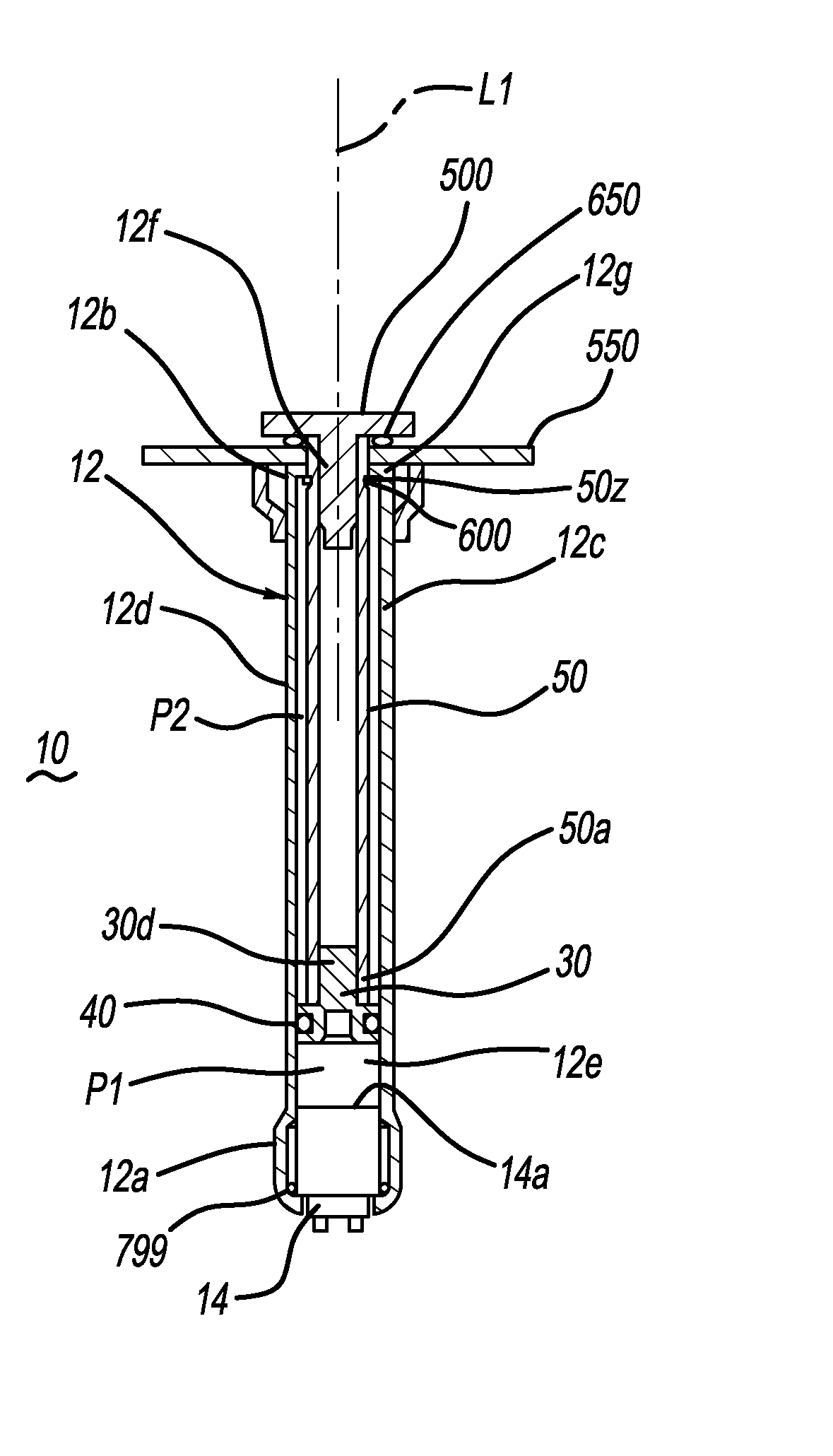
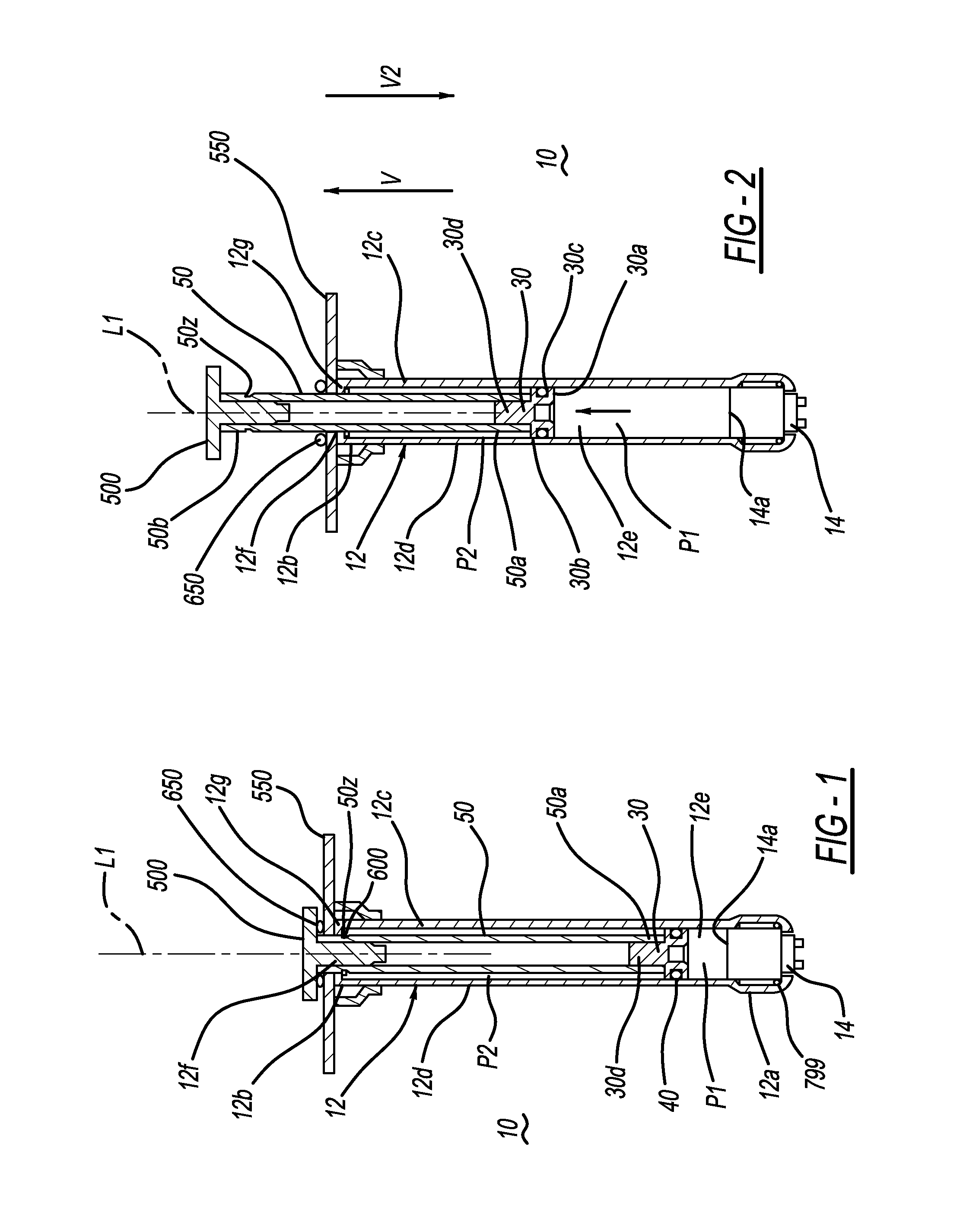
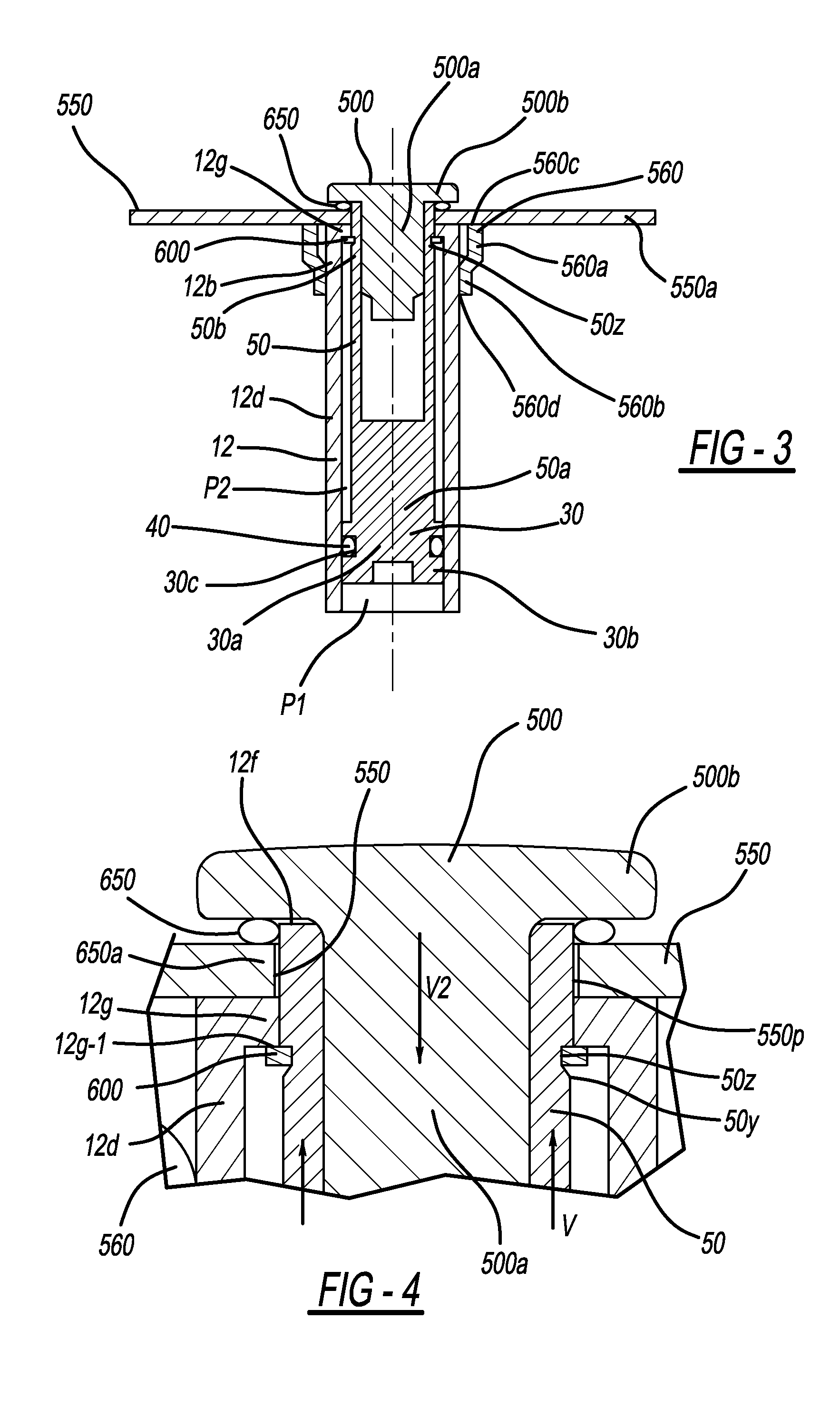
[0028]Referring to FIG. 5A, in an alternative embodiment 110 of the actuator, the bearing surface for the sealing means is formed by housing end 12b, which is structured so as to enable the striker 500 to compress the sealing means 650 against housing end wall 12g as shown, thereby permitting the mounting member 550 to be omitted or repositioned to another portion of the housing exterior. In this embodiment, opening 12f enables fluid communication therethrough between an exterior of the housing and the housing interior.

[0029]Piston 30 is slidably positioned within housing interior 12e. Piston has a base 30a with an outer wall 30b. A groove 30c is formed in wall 30b and is structured for receiving therein an O-ring 40 or another suitable resilient gas-tight seal. In a known manner, O-ring 40 resiliently slidingly contacts the interior surfaces of housing wall 12d, thereby providing a substantially gas-tight seal between the piston 30 and wall 12d. When piston 30 is positioned in hous...

embodiment 210

[0045]Referring to FIGS. 6A-6B, in another alternative embodiment 210 of the actuator, the bearing surface used for compressing the sealing means is provided by a reinforcing member 32 applied to the housing end 12b to reinforce or strengthen the housing end wall 12g against impact forces exerted by the piston 30 contacting the end wall at the end of the piston stroke (i.e., at full stroke).

[0046]In the embodiment shown in FIGS. 6A-6B, the reinforcing member 32 is in the form of a collar or cap attached to an end of housing 12 by welding or any other suitable method. However, the cap may have any alternative configuration suitable for the requirements of a particular application. In the embodiment shown in FIGS. 6A-6B, cap 32 has a base portion 32a and a wall 32b extending in a first direction from an edge of the base portion to define a cavity 32c structured for receiving therein a portion of housing second end 12b. Cap base portion 32a also has an opening 32d formed therein. Openi...


PUM


Abstract

A pressurized fluid-powered actuator includes a housing and a striker movably coupled to the housing. Resilient sealing means are positioned between the striker and the housing. The sealing means are compressible so as to seal an end of the housing responsive to a force exerted on the sealing means by the striker in a first direction toward the housing. Releasable retaining means are operatively coupled to the striker and are structured to prevent motion of the striker in a second direction opposite the first direction prior to activation of the actuator, and responsive to a reaction force in the second direction exerted on the striker by the sealing means when the sealing means is compressed.

Description

CROSS-REFERENCE TO RELATED APPLICATIONS[0001]This application claims the benefit of U.S. Provisional Application Ser. Nos. 62 / 020,973, filed on Jul. 3, 2014, the disclosure of which is incorporated herein by reference in its entirety.BACKGROUND OF THE INVENTION[0002]The embodiments described herein generally relate to pressurized fluid-powered actuators and, more particularly, to methods and / or mechanisms for environmentally sealing an actuator prior to actuator activation.[0003]In pressurized fluid-powered, piston driven actuators, fluid from a pressurized fluid source (for example, a pyrotechnic gas generator) is applied to a piston, thereby producing movement of the piston within the housing, and deployment or extension of an attached piston rod from the actuator housing. In this manner, force may be exerted by the piston rod on an actuatable element located exterior of the actuator housing.[0004]In certain actuator designs and applications, it is desirable to seal the actuator h...

Claims


Application Information

Patent Timeline
Patent Type & Authority Applications(United States)
IPC IPC(8): B60R21/38
CPCB60R21/38F15B15/1461F15B15/19
Inventor VAN HOOSER, JOSHUA D.WILMOT, LARRY M.KALLISKE, INGOABE, KAZUHIROGEORG, RASCH
Owner JOYSON SAFETY SYST ACQUISITION LLC
Learn More