
Display panel, manufacturing method thereof, and display device

a technology of display panel and manufacturing method, applied in the field of display panel, can solve problems such as complex processes

Inactive Publication Date: 2016-01-07
BOE TECH GRP CO LTD
View PDF2 Cites 6 Cited by
  • Summary
  • Abstract
  • Description
  • Claims
  • Application Information

AI Technical Summary

Benefits of technology

The present invention is related to a display panel that can reflect light from a backlight source to achieve good display function. The technical effect of the invention is that the first reflective layers become bent, allowing the light to be reflected to the second reflective layers and ultimately to the light-existing surface of the display panel.

Problems solved by technology

This process is complex.

Method used


Image

  • Display panel, manufacturing method thereof, and display device
  • Display panel, manufacturing method thereof, and display device
  • Display panel, manufacturing method thereof, and display device

Examples


Embodiment Construction

[0058]To enable those skilled in the art to better understand the technical solutions of the present invention, the present invention will be further described below in detail in conjunction with the accompanying drawings and the specific implementations.

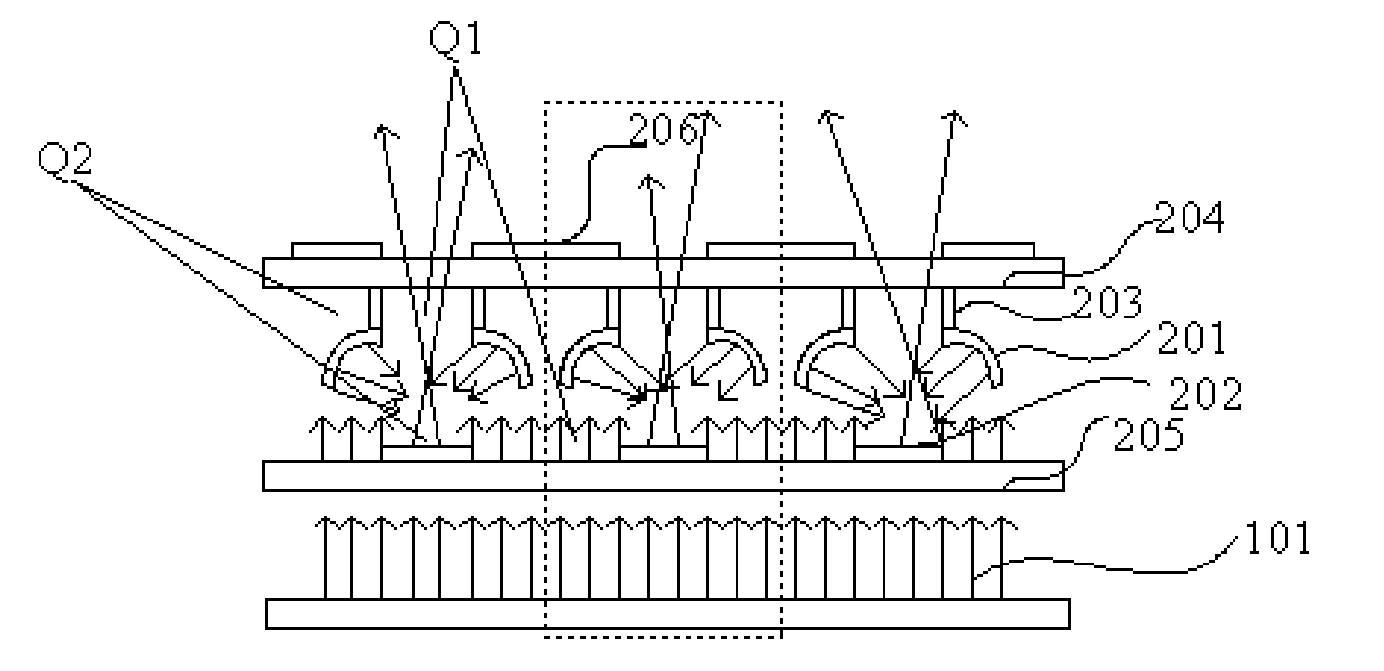
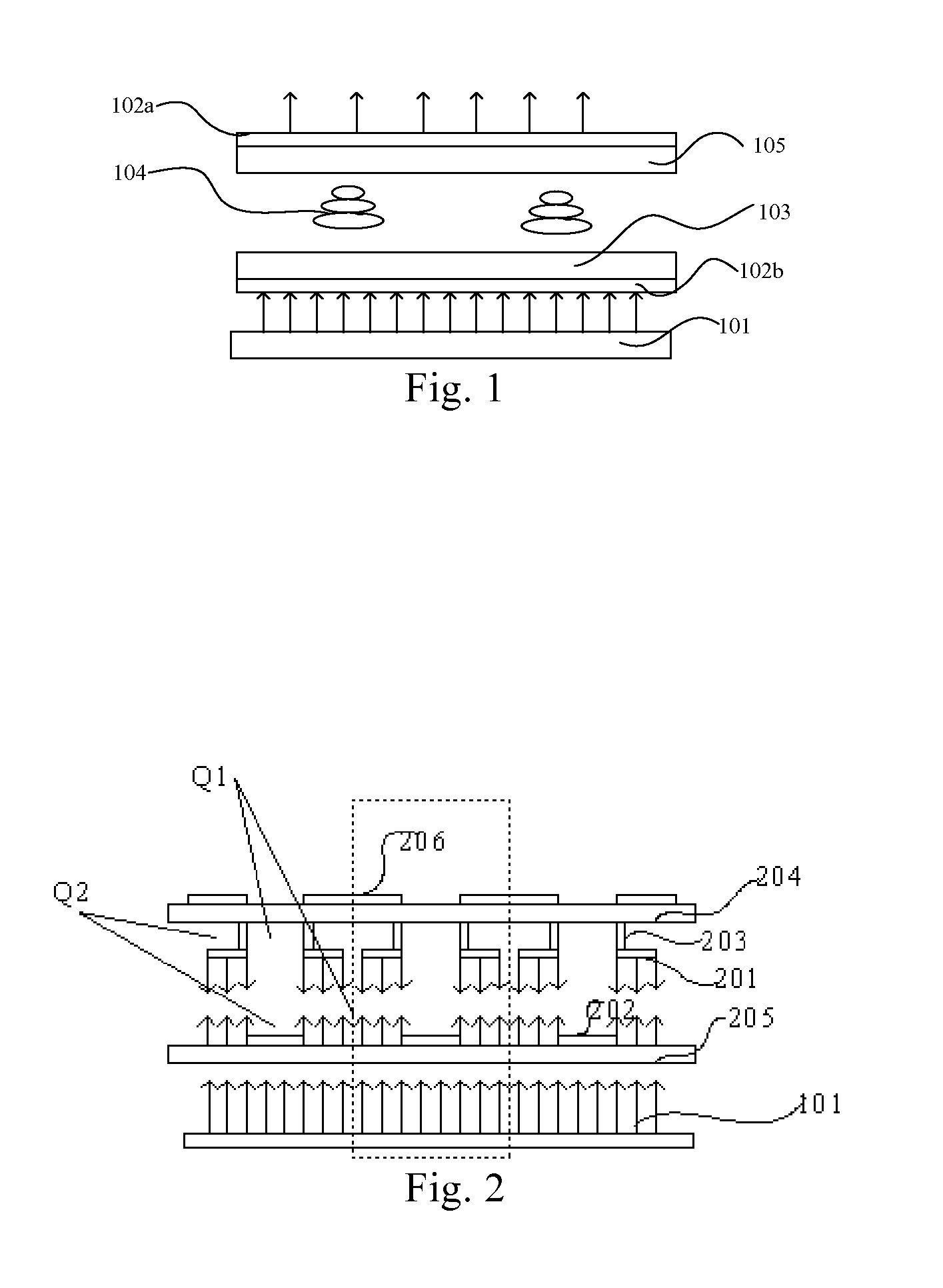
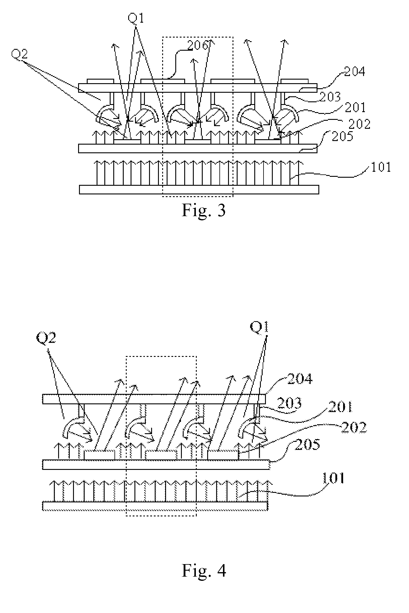
[0059]FIG. 2 is a schematic diagram of a structure of a display panel with no voltage applied thereto according to an embodiment of the present invention, FIG. 3 is a schematic diagram of a structure of a display panel with a voltage applied thereto according to an embodiment of the present invention, and FIG. 4 is a schematic diagram of a structure of a display panel according to another embodiment of the present invention.

[0060]Referring to FIGS. 2 to 4, a display panel according to an embodiment of the present invention comprises a first substrate 204 and a second substrate 205 provided opposite to each other, and each of the first substrate 204 and the second substrate 205 comprises a plurality of photic areas Q1 and a plurality...


PUM


Abstract

The present invention provides display panel and manufacturing method thereof, and display device comprising the display panel. The display panel comprises: a first substrate and a second substrate provided opposite to each other, each of which comprises a plurality of photic areas and a plurality of shading areas; a plurality of pixel units formed between the first substrate and the second substrate; and a plurality of control units corresponding to the plurality of pixel units, respectively. In each pixel unit, a projection of the shading area of the first substrate on the second substrate completely covers the photic area of the second substrate. On a side of the first substrate opposite to the second substrate, a first reflective layer which is bendable is provided on each of the shading areas of the first substrate, and on a side of the second substrate opposite to the first substrate, a second reflective layer is provided on each of the shading areas of the second substrate. The first reflective layers, in a bent state, reflect light reaching the first reflective layers to the second reflective layers, and the second reflective layers reflect the light reflected thereto to the photic areas of the first substrate.

Description

FIELD OF THE INVENTION[0001]The present invention relates to the field of display technology, and particularly to a display panel and a manufacturing method thereof, and a display device comprising the display panel.BACKGROUND OF THE INVENTION[0002]Display devices may be classified into two categories: a light-emitting type and a non-light-emitting type. The light-emitting type display devices include organic light-emitting diode (OLED) display devices and the like, and the pixels thereof themselves can emit required light. The non-light-emitting type display devices mainly include liquid crystal display devices, and the pixels thereof do not emit light per se and need to use light from backlight sources to display.[0003]As shown in FIG. 1, a basic configuration of a liquid crystal display (LCD) device comprises a backlight source 101 and a liquid crystal display panel.[0004]The liquid crystal display panel may comprise an array substrate 103, a color filter substrate 105 and liquid...

Claims


Application Information

Patent Timeline
IPC IPC(8): G02B26/08G02B1/12G02B5/20
CPCG02B26/0825G02B1/12G02B5/201G02B26/0841G06F3/011
Inventor ZHAO, JISHENG
Owner BOE TECH GRP CO LTD
Learn More