Female terminal fitting

Active Publication Date: 2016-01-07
SUMITOMO WIRING SYST LTD
View PDF83 Cites 8 Cited by
  • Summary
  • Abstract
  • Description
  • Claims
  • Application Information

AI Technical Summary

Benefits of technology

[0011]The resilient contact piece may be wider on a base end part side than on the free end part. In this way, a resilient force reduction of the resilient contact piece is avo...

Problems solved by technology

Further, even if the auxiliary spring piece is going to excessively swing in the width direction, the excessive deflection...

Method used


Image

  • Female terminal fitting
  • Female terminal fitting
  • Female terminal fitting

Examples


Embodiment Construction

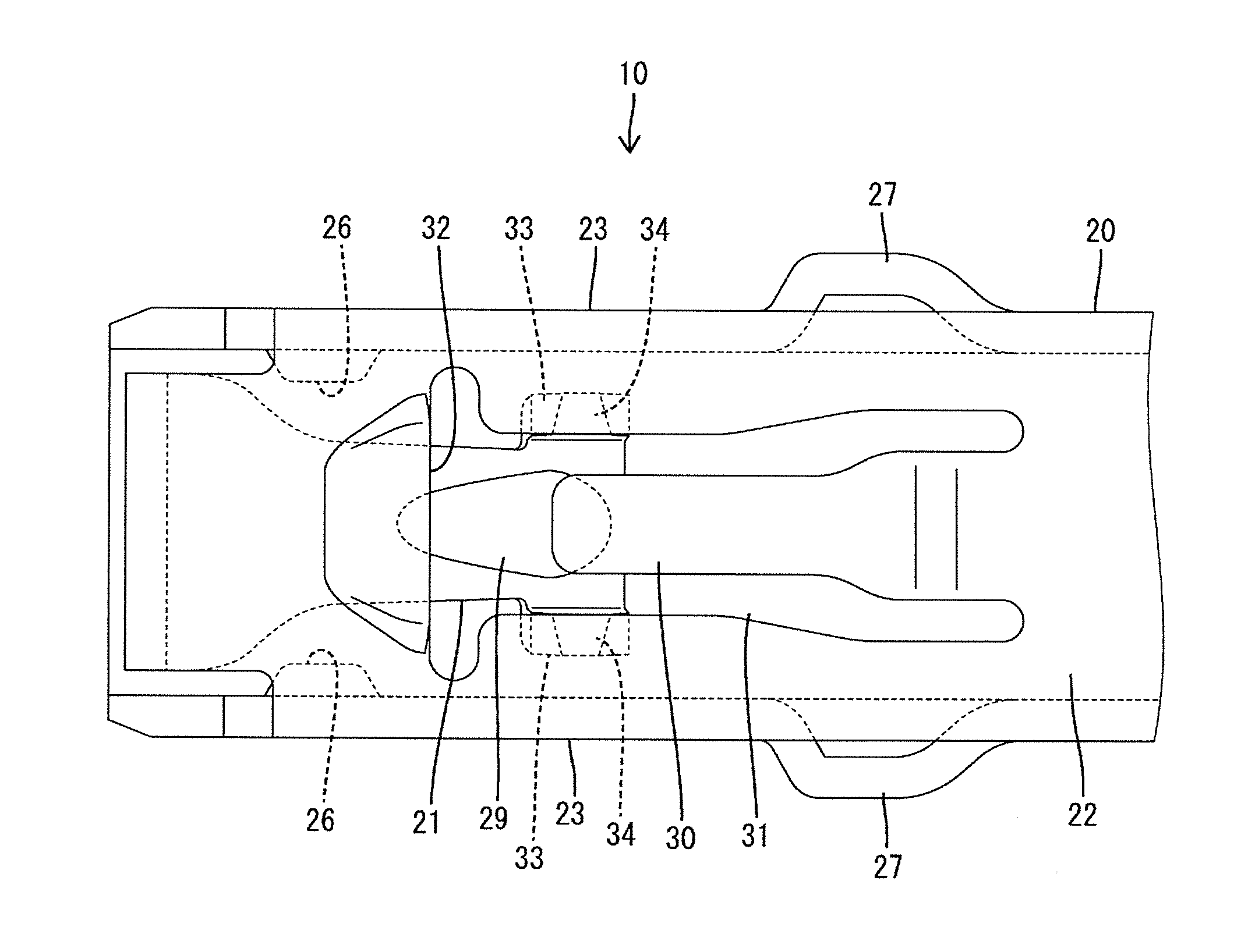
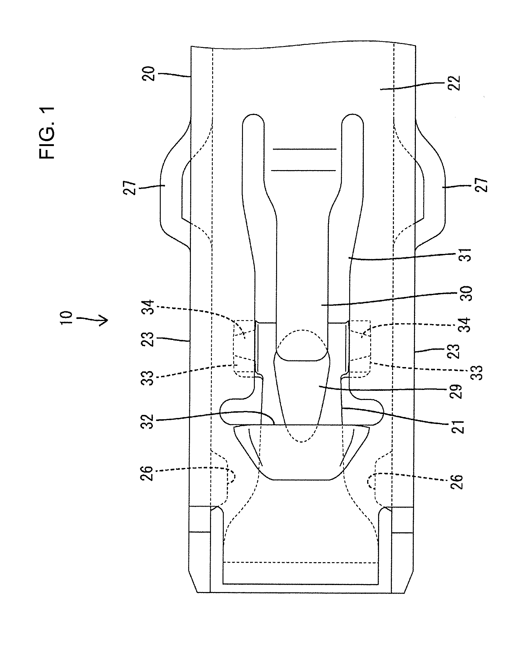
[0017]One embodiment of the present disclosure is described in detail with reference to FIGS. 1 to 5. A female terminal fitting 10 of this embodiment is formed such as by bending an electrically conductive metal plate and includes a main body portion 20 for receiving a mating male tab 90 and a resilient contact piece 21 deflectably arranged in the main body portion 20. Note that although the female terminal fitting 10 includes a part to be connected to a wire behind the main body portion 20, this part is neither described nor shown here.

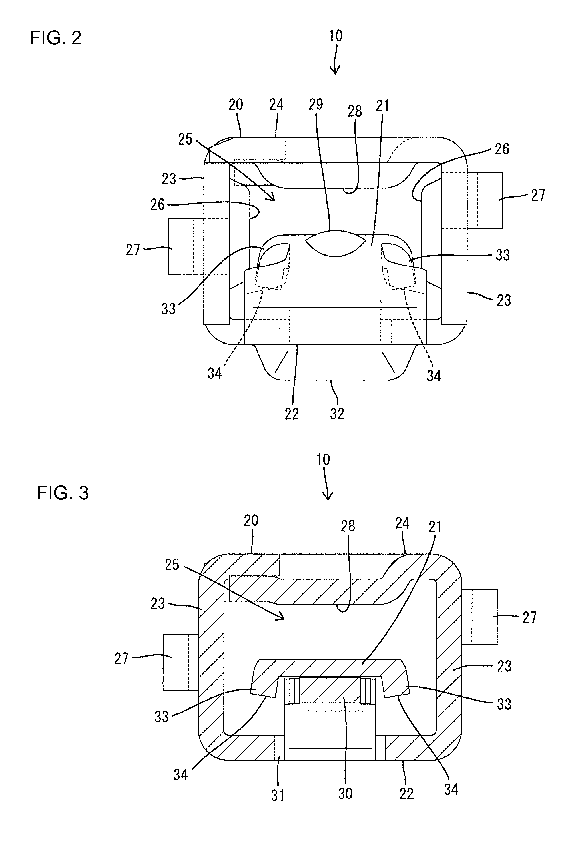
[0018]The main body portion 20 is in the form of a rectangular tube penetrating in a front-back direction and, as shown in FIGS. 2 and 3, includes a base wall 22 extending substantially along a width direction, a pair of side walls 23 standing up from opposite side edges of the base wall 22 (opposite ends in the width direction) and a facing wall 24 bridged from the upper end of one of the both side walls 23 to the upper end of the other. A tab inser...


PUM


Abstract

A female terminal fitting (10) is provided with a tubular main body portion (20) into which a mating male tab (90) is to be inserted, and a resilient contact piece (21) deflectably arranged in the main body portion (20). The resilient contact piece (21) is resiliently deformed toward a base wall (22) of the main body portion (20) to resiliently come into contact with the male tab (90) when the male tab (90) is inserted into the main body portion (20). An excessive deflection regulating piece (33) for regulating excessive deflection of the resilient contact piece (21) by coming into contact with the base wall (22) of the main body portion (20) is integrally provided to the resilient contact piece (21).

Description

BACKGROUND[0001]1. Field of the Invention[0002]The present invention relates to a female terminal fitting.[0003]2. Description of the Related Art[0004]A female terminal fitting disclosed in Japanese Unexamined Patent Publication No. 2003-243076 includes a tubular main body portion (called an “electrical contact portion” Japanese Unexamined Patent Publication No. 2003-243076) into which a male tab is to be inserted, and a resilient contact piece deflectably arranged in the main body portion and to be resiliently brought into contact with the male tab (called a “male terminal” in Japanese Unexamined Patent Publication No. 2003-243076) inserted into the main body portion. Further, a part of a side wall of the main body portion is cut and bent inwardly to prevent excessive deflection of the resilient contact piece, thereby forming an excessive deflection preventing piece.[0005]In the above case, since a hole is made on the side wall as the excessive deflection preventing portion is form...

Claims


Application Information

Patent Timeline
IPC IPC(8): H01R4/48
CPCH01R4/48H01R13/113
Inventor CHIKUSA, TAKAHIRO
Owner SUMITOMO WIRING SYST LTD
Why Eureka
Try Eureka