
Interchangeable lens digital camera

a digital camera and interchangeable lens technology, applied in the field of interchangeable lens digital cameras, can solve the problems of cmos sensor, cmos sensor, more affected by noise, inferior image quality, etc., and achieve the effect of reducing noise and reducing distortion

Active Publication Date: 2016-01-07
FUJIFILM CORP
View PDF3 Cites 34 Cited by
  • Summary
  • Abstract
  • Description
  • Claims
  • Application Information

AI Technical Summary

Benefits of technology

The present invention provides an interchangeable lens digital camera that can correct rolling shutter distortion in the live view image without delay. The camera detects the shake of the interchangeable lens and sends the deviation information to the camera body through either the serial or condition communication unit. Using this deviation information, the camera body can correct the rolling shutter distortion, even if it does not have a shake detection sensor. This is possible because the deviation information is available quickly, allowing for quicker correction without displaying a delay in the live view image.

Problems solved by technology

Compared to CCD image sensors, CMOS type image sensors (hereinafter referred to as CMOS sensors) have conventionally been more affected by noises and inferior in image quality.
However, because of the difference in exposure timing between the pixels or between the scanning lines, the image captured according to the rolling shutter method may have a distortion called rolling shutter distortion if the digital camera sways during the imaging due to camera shake, panning or the like, or if the subject moves during the imaging.
The digital camera loaded with a CMOS sensor has a problem that the rolling shutter distortion occurs also in the live view image and bothers the photographer.
However, as described above, since the image data processor in JPA No. 2012-080490 calculates the shift amounts of a subject image between the adjacent scanning lines, as the subject image is moving relatively to the imaging plane of the CMOS sensor, there will be a time lag in displaying the live view image if it takes much time for this calculation.
However, the shake compensation method by moving the image sensor or the compensation lens is merely effective for correcting a blur due to instability of the camera such as camera shake, but not suitable for correcting a picture deviation caused by a large motion such as the panning of the camera.
Because a CMOS sensor and an image data processor are built in the camera body, it is impossible to correct the rolling shutter distortion of the live view image on the camera body side on the basis of the detection result from the shake detection sensor of the interchangeable lens.

Method used


Image

  • Interchangeable lens digital camera
  • Interchangeable lens digital camera
  • Interchangeable lens digital camera

Examples


first embodiment

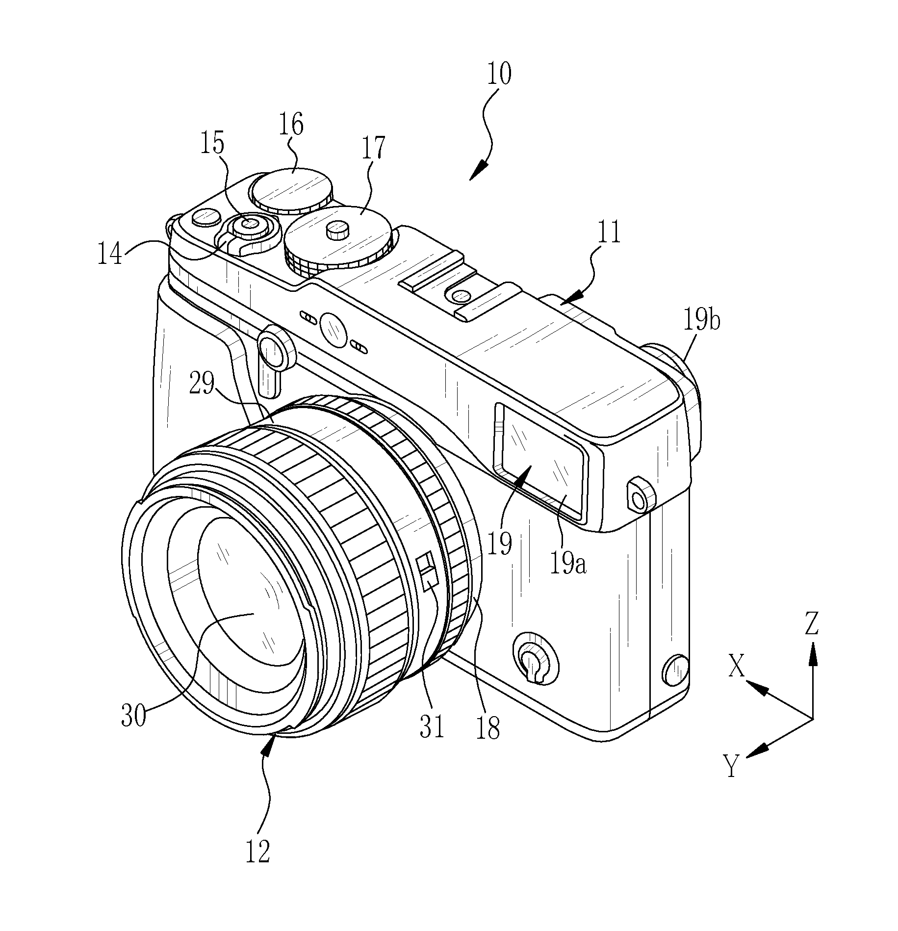
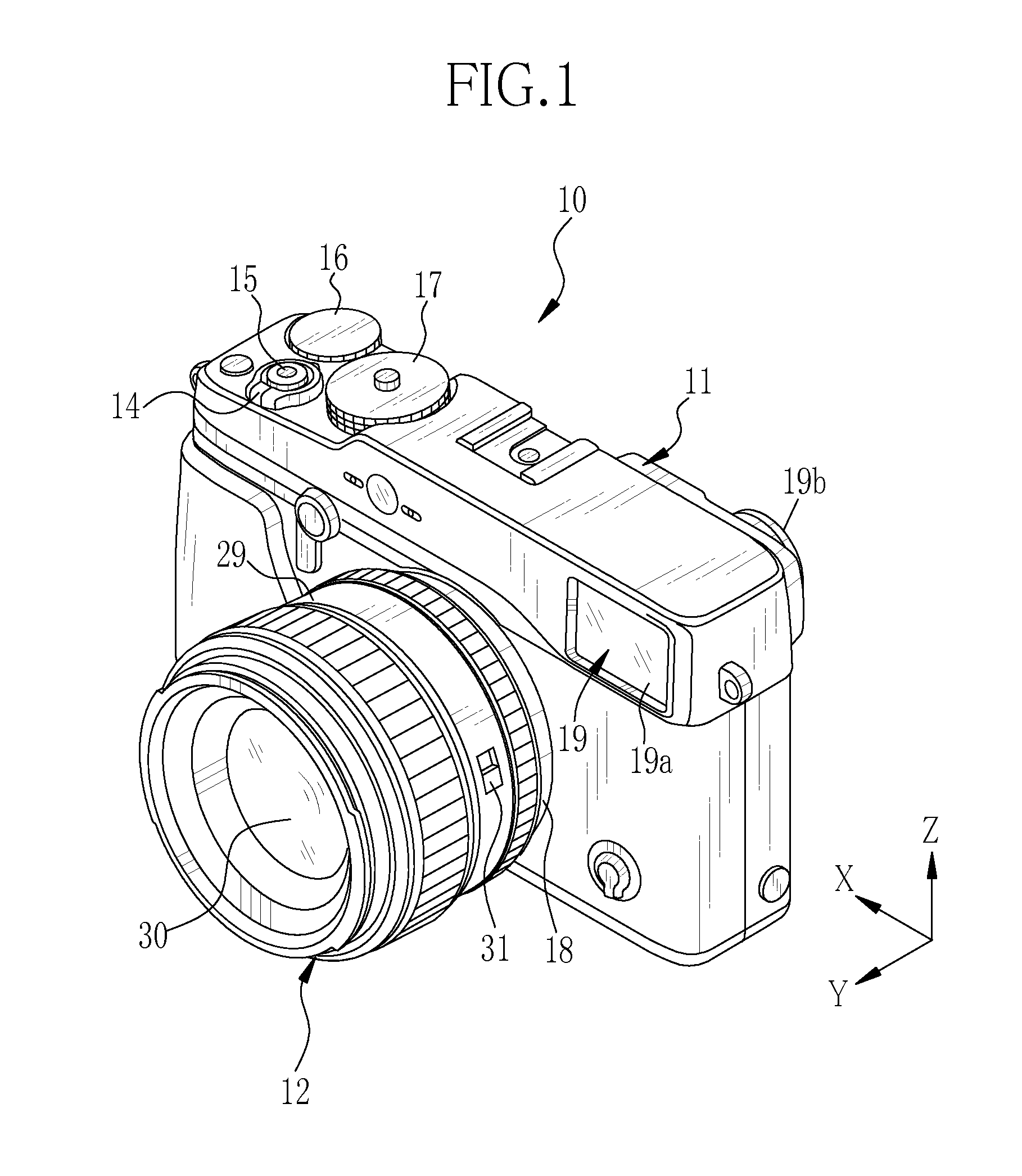
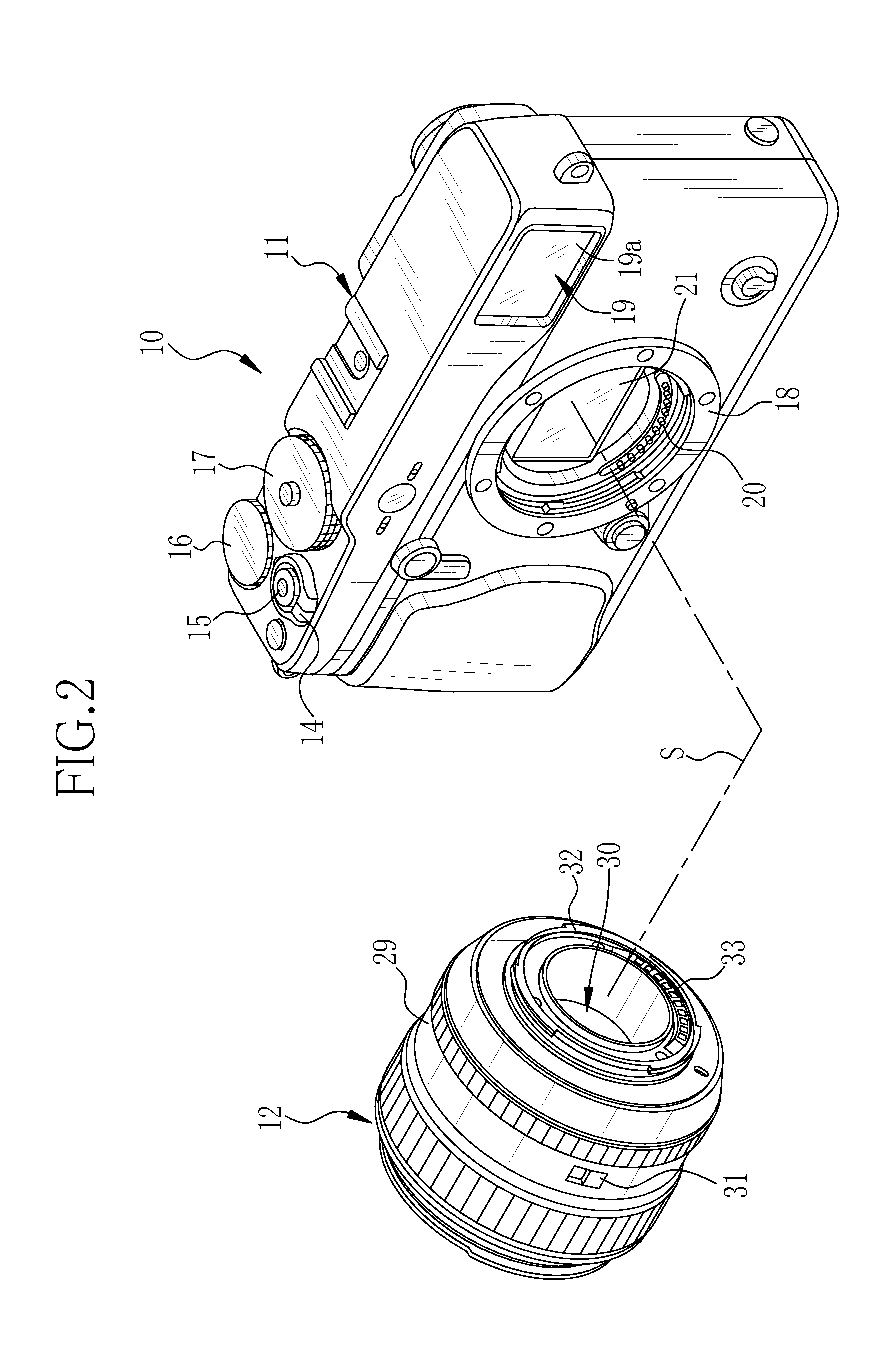
[0062]In FIGS. 1 and 2, a lens interchangeable digital camera (hereinafter referred to as a camera) embodying the present invention is provided with a camera body 11, an interchangeable lens 12 that is detachably attachable to the camera body 11, and communication units that are electrically connected by attaching the interchangeable lens 12 to the camera body 11, enabling communication between the camera body 11 and the interchangeable lens 12. The camera 10 is a mirrorless single-lens reflex digital camera capable of using an appropriate interchangeable lens 12 for the purpose or intention of the photography. The camera 10 acquires an image of a subject through a CMOS sensor 21 that is integrated in the camera body 11. The camera 10 also has an optical shake compensation device 13 (refer to FIG. 4) which is integrated in the interchangeable lens 12 and makes a compensation for a camera shake so as to stabilize the optical image. The optical shake compensation device 13 may be call...

second embodiment

[0115]The second embodiment is configured to execute the second process even while the shake compensation device 13 is active under certain conditions that will lower the correcting effect on a rolling shutter distortion by the shake compensation device 13. As shown in FIG. 14, after the start of the shake detection (S12), the lens controller 36 starts determinations about a shake compensation limit and the panning (S32). Then, the determination result on the shake compensation limit and the determination result on the panning are transmitted to the body controller 67 through the serial communication unit 90, for example, along with the mode information on the shake compensation device 13 (S33).

[0116]For the determination on the shake compensation limit, the amount of a shake detected by the shake detection sensor 40 is compared with the shake compensation limit of the shake compensation device 13, to determine whether the shake amount exceeds the shake compensation limit or not. Th...

third embodiment

[0128]The third embodiment is configured to switch over between the first and second processes depending upon the operating conditions of the electronic zooming. As shown in FIG. 16, the electronic zooming is performed by the image data processor 72, cropping an image part from a live view image 120 within a zooming zone 121, which is determined according to a zoom magnification designated by the zooming operation, and enlarging the cropped image part to be displayed as a live view image 120a on the image display unit 24. As the image part within the zooming zone 121 is enlarged for the electronic zooming, also a rolling shutter distortion would be enlarged. Even while the rolling shutter distortion before the enlargement is in such a degree that does not need a correction, the enlarged distortion may have to be corrected. Therefore, during the electronic zooming, there may be cases requiring the second process.

[0129]According to the third embodiment, as shown in FIG. 17, the body c...


PUM


Abstract

Provided is an interchangeable lens digital camera that is capable of correcting a rolling shutter distortion in a live view image without delay in displaying the image. At the start of live view imaging, a lens controller in an interchangeable lens controls a shake detection sensor to detect the direction and amount of a shake, and produces deviation information on the basis of shake detection signals from the shake detection sensor, the deviation information indicating fluctuation in direction and amount of the shake for one frame of the live view image in the form of a parameter. The deviation information is transmitted to a body controller of a camera body through a serial communication unit, to correct the rolling shutter distortion on the basis of the deviation information.

Description

CROSS-REFERENCE TO RELATED APPLICATIONS[0001]This application is a Continuation of PCT International Application No. PCT / JP2014 / 054635 filed on Feb. 26, 2014, which claims priority under 35 U.S.C §119(a) to Japanese Patent Application No. 2013-066285 filed Mar. 27, 2013. The above application is hereby expressly incorporated by reference, in its entirety, into the present application.BACKGROUND OF THE INVENTION[0002]1. Field of the Invention[0003]The present invention relates to an interchangeable lens digital camera.[0004]2. Description Related to the Prior Art[0005]As an image sensor mounted in a digital camera, a CMOS (complementary metal oxide semiconductor) type image sensor is known. Compared to CCD image sensors, CMOS type image sensors (hereinafter referred to as CMOS sensors) have conventionally been more affected by noises and inferior in image quality. However, recent various improvements provide CMOS sensors with higher image quality enough for employing the CMOS sensors...

Claims


Application Information

Patent Timeline
IPC IPC(8): H04N5/232G03B17/14
CPCH04N5/23209H04N5/23251G03B17/14G03B5/00G03B2206/00G03B2217/005H04N23/55H04N23/663H04N23/67H04N23/6812H04N23/689H04N23/681
Inventor IMAMURA, KENSHI
Owner FUJIFILM CORP
Learn More