Particle therapy device and method for setting dose calibration factor

a technology of dose calibration factor and particle therapy, which is applied in the field of particle therapy device, can solve the problems of difficult to convert the value simply into a dose, and the inability to place a dosimeter in the body as the irradiation target, and achieve the effect of high-quality irradiation

Active Publication Date: 2016-01-14
HITACHI LTD
View PDF3 Cites 23 Cited by
  • Summary
  • Abstract
  • Description
  • Claims
  • Application Information

AI Technical Summary

Benefits of technology

[0012]According to the particle therapy device and the method for setting a dose calibration factor of the invention, since it is possible to precisely calibrate a dose even for a layer for which no actual dose has been measured, a highly accurate irradiation in line with the treatment plan can be achieved.

Problems solved by technology

In employing either irradiation method, it is required to precisely recognize a dose during irradiation in order to perform irradiation in line with a target dose planned by a treatment plan device; however, it is impossible to place (implant) a dosimeter in a body as the irradiation target.
However, since the particle beam is not a parallel beam, but a fan beam or cone beam having a spread, variations in dose due to positional differences in the body within a diseased site are not reflected in the measurement value by the dose monitor, so that it is difficult to convert the value simply into an actual dose.

Method used


Image

  • Particle therapy device and method for setting dose calibration factor
  • Particle therapy device and method for setting dose calibration factor
  • Particle therapy device and method for setting dose calibration factor

Examples


embodiment 1

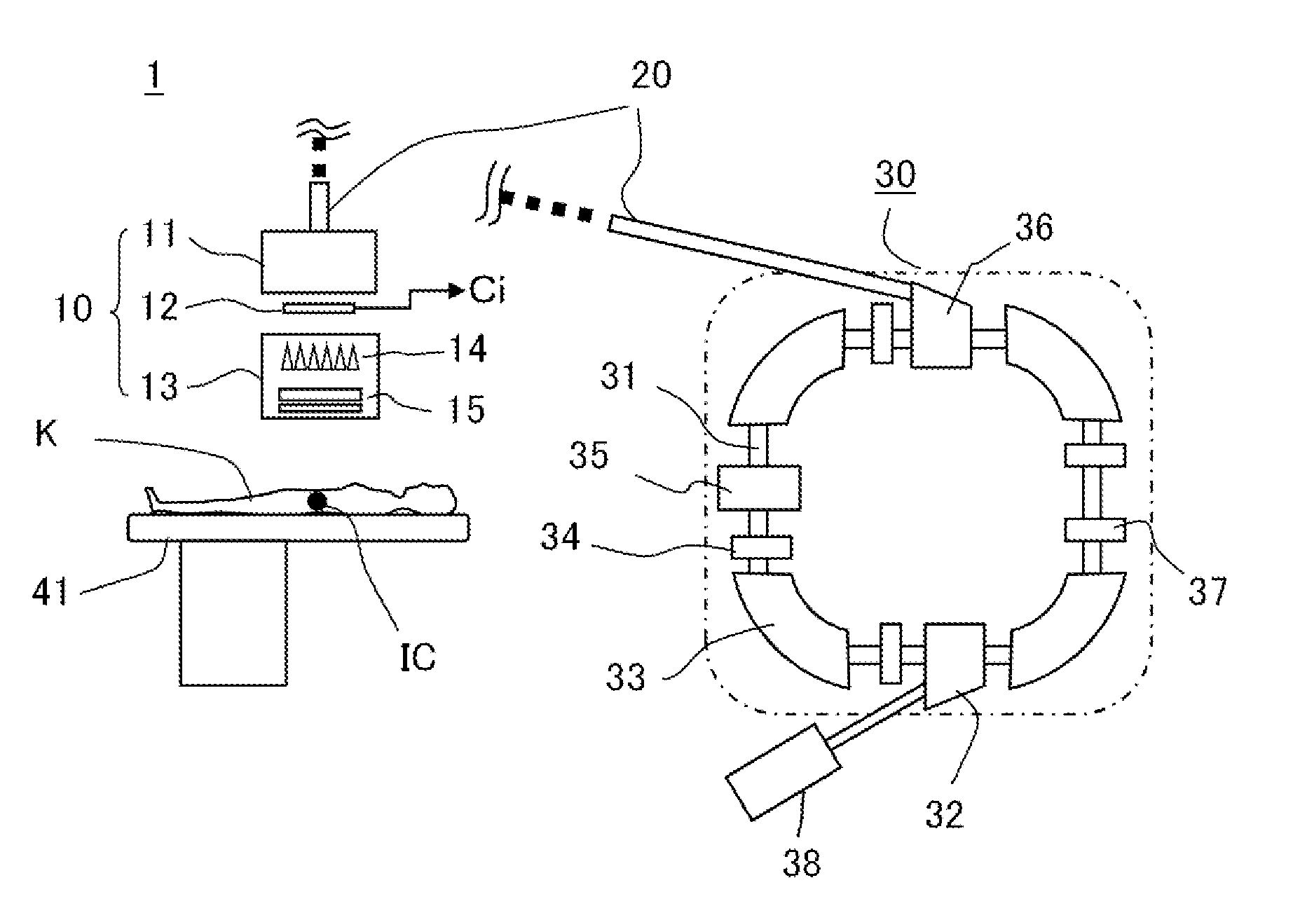
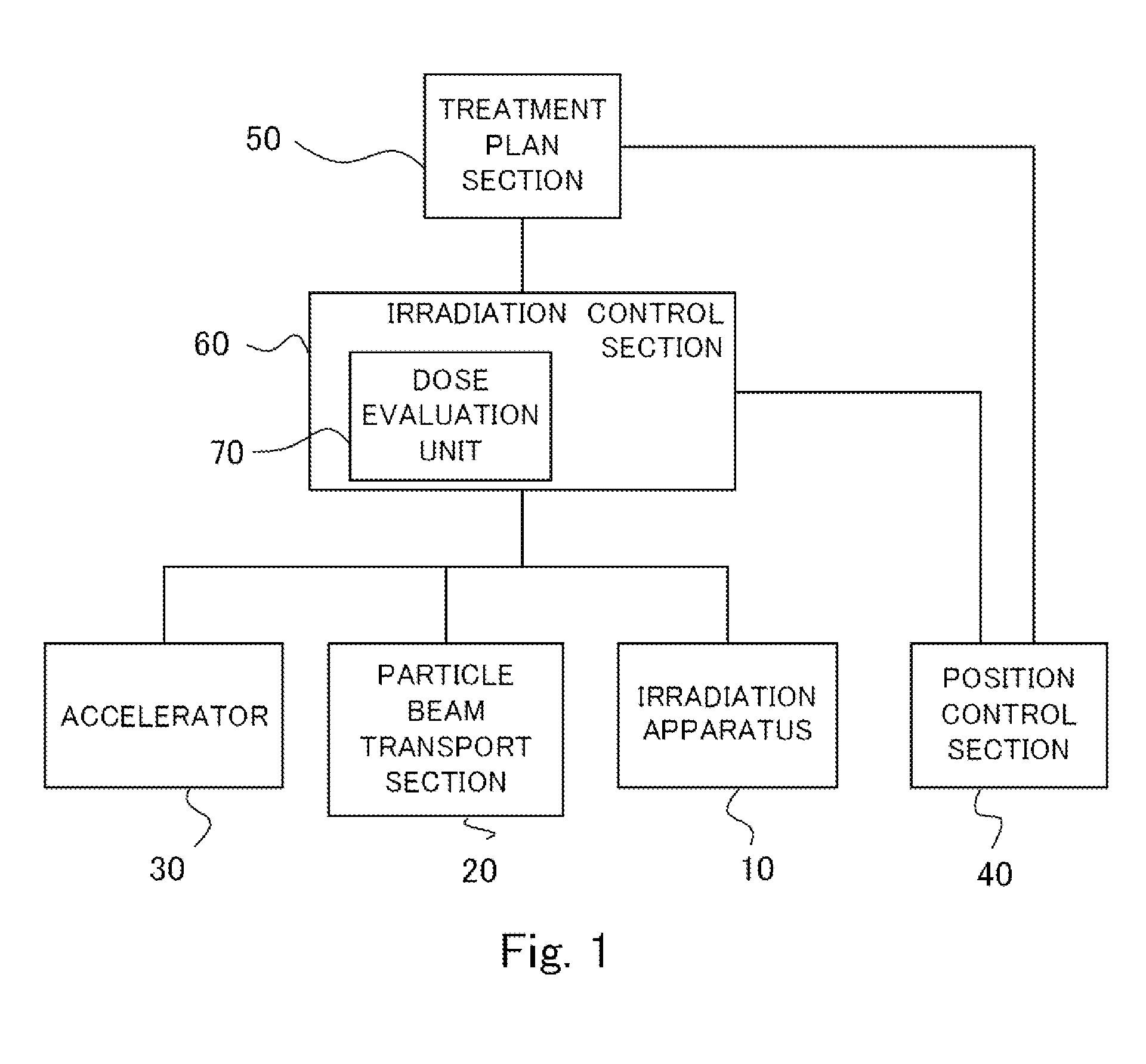
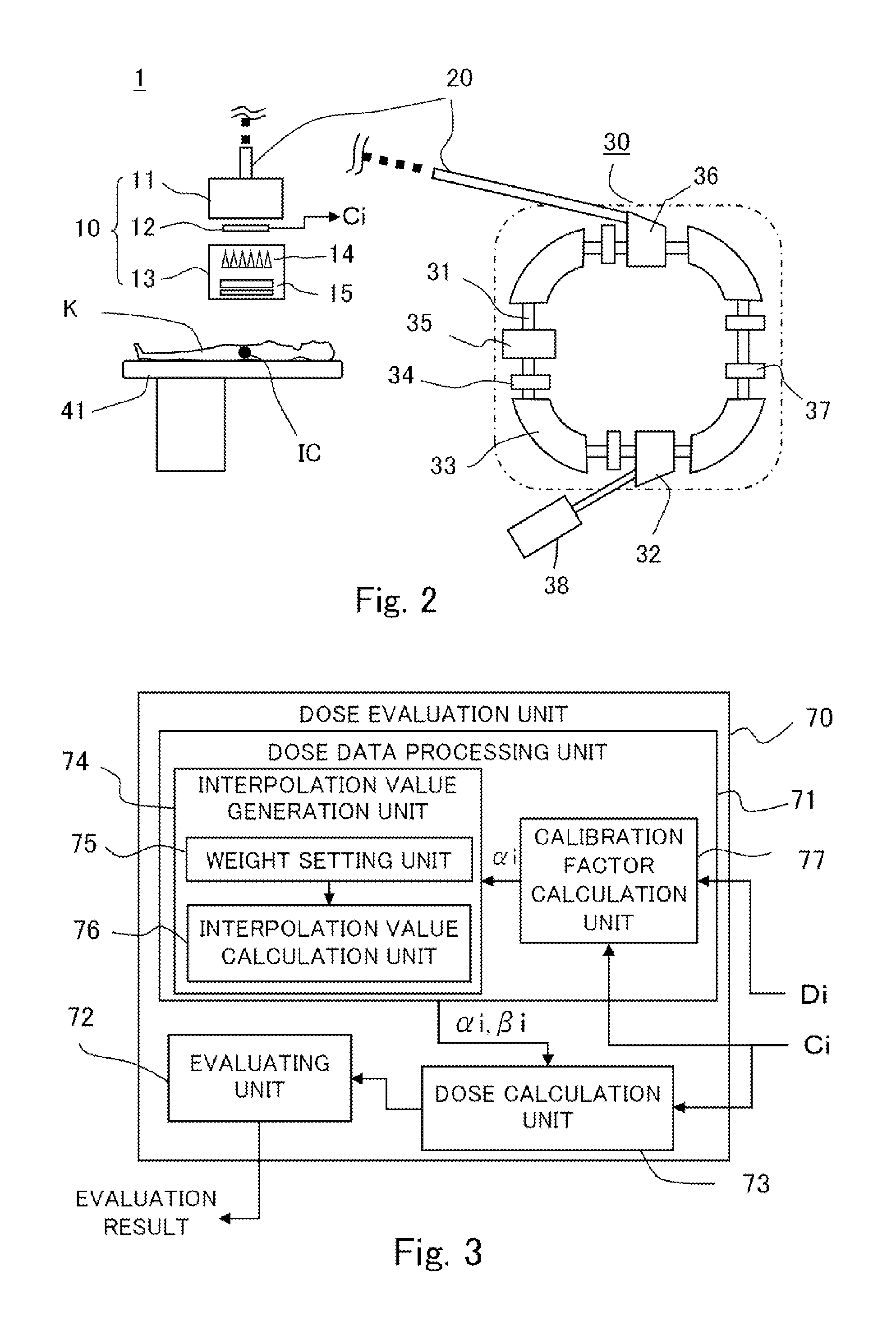
[0019]Hereinafter, description will be made about a configuration of a particle therapy device according to Embodiment 1 of the invention. FIG. 1 to FIG. 5 are for illustrating the particle therapy device and a method for setting a dose calibration factor, according to Embodiment of the invention, in which FIG. 1 is an overall functional-block diagram for illustrating a configuration of the particle therapy device and the method for setting a dose calibration factor; FIG. 2 is an overall diagram for schematically illustrating an apparatus configuration at the time of performing a particle beam therapy; FIG. 3 is a functional block diagram of a dose evaluation unit, for illustrating a configuration of the particle therapy device and the method for setting a dose calibration factor; FIG. 4 is a diagram for illustrating an apparatus configuration at the time of performing a dose calibration in a calibration stage; and FIG. 5 is a graph for calculating a dose calibration factor for maki...

embodiment 2

[0055]In Embodiment 1, the description has been made about a case where, at the calculation of the interpolation value βi, weighting is performed with attention to the water-equivalent depth; however, in Embodiment 2, weighting is performed in consideration also of an irradiation condition other than the water-equivalent depth. FIG. 6 is for illustrating a particle therapy device or a method for setting a dose calibration factor according to Embodiment 2, and is a graph representing schematically a relationship between water-equivalent depths of respective layers with different irradiation conditions with respect to the particle therapy device and actually-measured dose calibration factors. Note that, for the configuration related to the particle therapy device and its control, the figures used in Embodiment 1 will also be used, and similar parts therein will be omitted from description.

[0056]In Embodiment 2, focusing is taken to the fact that, when a variation occurs in water-equiv...

embodiment 3

[0075]In Embodiment 2, the description has been made about a case of using only the dose calibration factors of the layers whose conditions are the same as that of a layer that wants to obtain the interpolation value. However, in practice, the region required for the polynomial model is a region having a specified width that is “deeper than the depth allowable for measurement by the water phantom”. Thus, in that region, an influence due to a plurality of parameters exists. Namely, in that region, an influence emerges due to “accelerator's parameter”, “range-shifter's parameter”, “wobbler radius parameter”, etc., in their overlapped manner. Thus, in the particle therapy device or the method for calibrating an irradiation dose according to Embodiment 3, a black / white decision is not taken whether “to use / not to use” each dose calibration factor as data for obtaining the interpolation value, but weighting is taken on the factor in view of a plurality of conditions. Note that, also in E...


PUM


Abstract

An irradiation apparatus radiates a particle beam after forming the beam for plural layers. A dose monitor measures a dose in real time. A dose evaluation unit evaluates an irradiation dose for each layer on the basis of a value measured by the dose monitor and a dose calibration factor set for each layer. An irradiation control section performs radiation control for each layer on the basis of an evaluation result of the dose evaluation unit. An interpolation value generation unit uses actual-measurement dose-calibration factors obtained by radiating a particle beam to a simulated phantom provided with a calibration dosimeter, to generate an interpolation estimation value of the dose calibration factor. For each layer subject to the interpolation value, and based on an irradiation condition of that layer, the interpolation value generation unit performs weighting on each of the actual-measurement dose-calibration factors.

Description

TECHNICAL FIELD[0001]The present invention relates to a particle therapy device for treating a cancer or the like, by radiating a particle beam thereto, and in particular, to a particle therapy device that employs a layer-stacking conformal irradiation method or a scanning irradiation method, as well as to a method for setting a dose calibration factor.BACKGROUND ART[0002]As an irradiation method employed in a particle therapy device, there is known: a layer-stacking conformal irradiation method in which an irradiation target is virtually partitioned into a plurality of layers in order of depth from the body surface and irradiation is performed for every layer; and a scanning irradiation method. In employing either irradiation method, it is required to precisely recognize a dose during irradiation in order to perform irradiation in line with a target dose planned by a treatment plan device; however, it is impossible to place (implant) a dosimeter in a body as the irradiation target....

Claims


Application Information

Patent Timeline
Patent Type & Authority Applications(United States)
IPC IPC(8): A61N5/10
CPCA61N5/1067A61N2005/1076A61N5/1075A61N5/1071A61N2005/1087
Inventor HARADA, HISASHIIKEDA, MASAHIROTAKAHASHI, OSAMUINA, NOBUHIKOPU, YUEHUIWATA, TAKAAKI
Owner HITACHI LTD
Why Eureka
Try Eureka