Improved Spiral Wound Element Construction

Inactive Publication Date: 2016-01-14
AQUA MEMBRANES
View PDF7 Cites 43 Cited by
  • Summary
  • Abstract
  • Description
  • Claims
  • Application Information

AI Technical Summary

Problems solved by technology

While this feed spacer is necessary to maintain open and uniform axial flow between the laminated structure, it is also a source of flow restriction and pressure drop within the axial flow channel and also presents areas of restriction of flow and contact to the membrane that contribute significantly to membrane fouling via biological growth, scale formation, and particle capture.

Method used


Image

  • Improved Spiral Wound Element Construction
  • Improved Spiral Wound Element Construction
  • Improved Spiral Wound Element Construction

Examples


Embodiment Construction

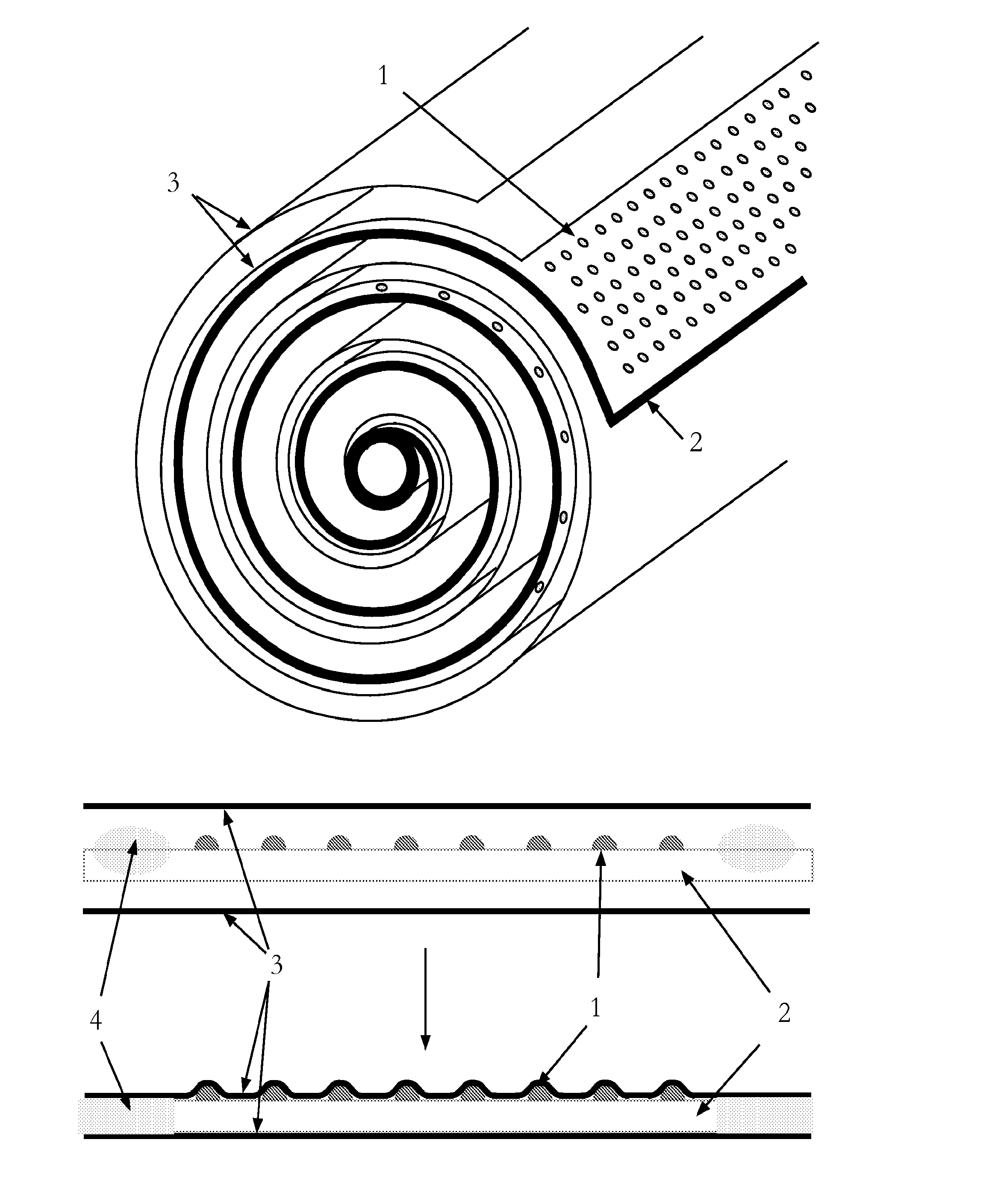
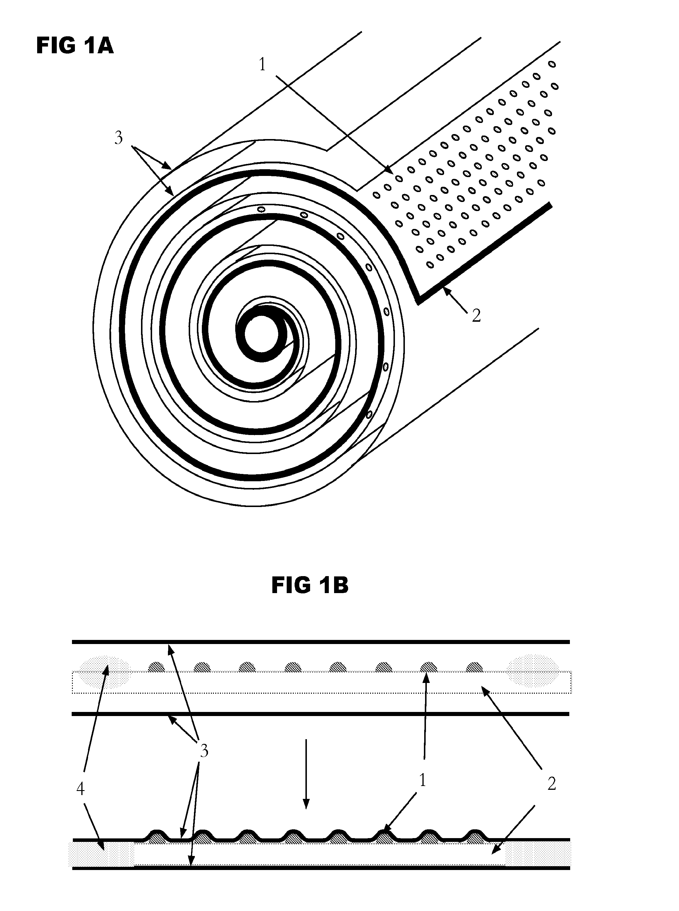
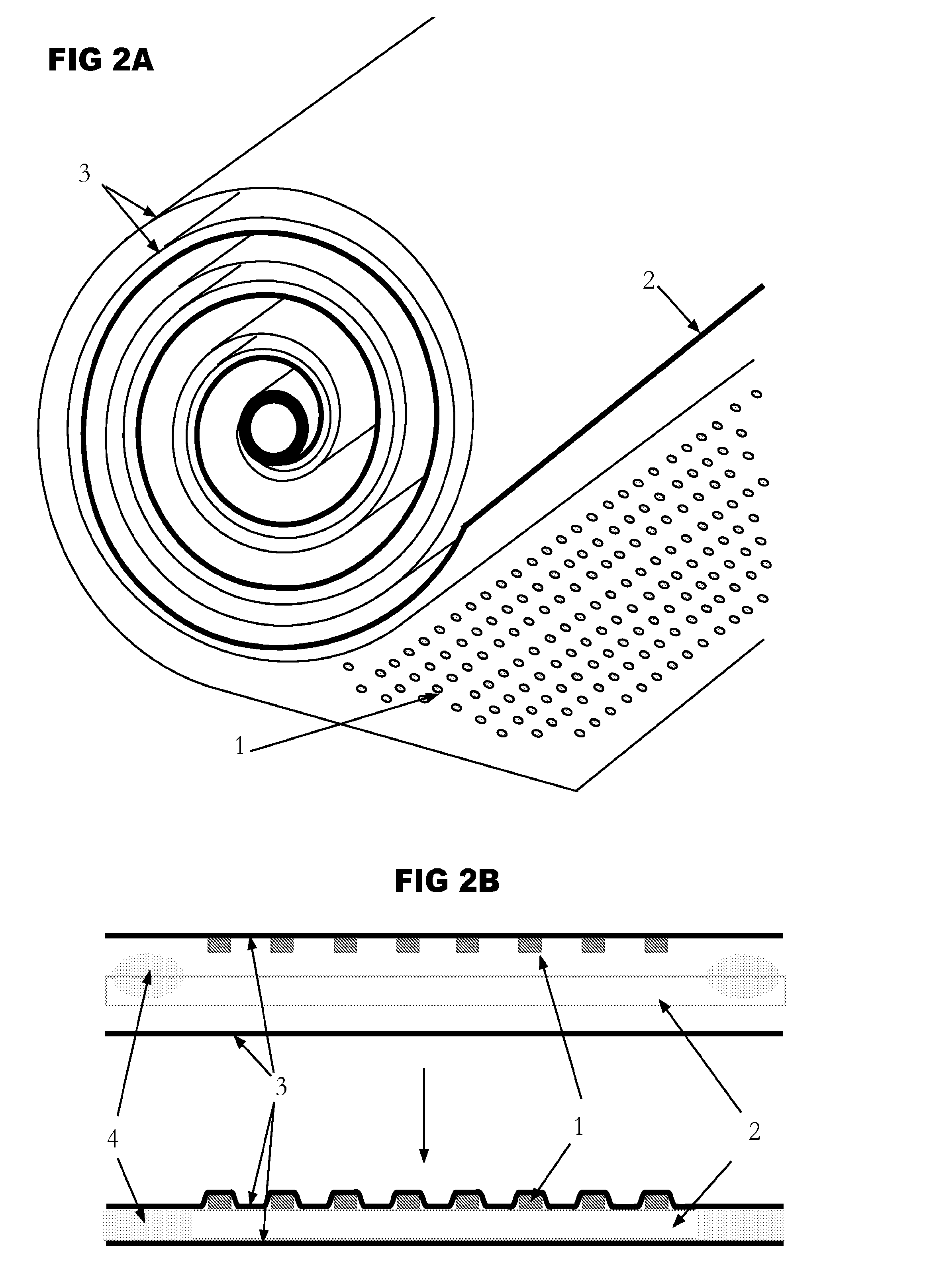
[0007]Embodiments of the present invention provide replacement of conventional separate feed spacer mesh with features placed, deposited or integrated on or into either the porous permeate carrier, the inactive side of the membrane sheet, or select portions of the membrane surface.

BRIEF DESCRIPTION OF THE DRAWINGS

[0008]FIG. 1A&FIG. 1B are views of spacer features deposited on the permeate carrier within a spiral-wound element.

[0009]FIG. 2A&FIG. 2B are views of spacer features deposited on the non-feed surface (inactive or support surface) of the membrane.

[0010]FIG. 3 is a view of edge spacing strips placed between a folded membrane leaf.

[0011]FIG. 4A is a view of a solid edge spacing strip being cut away from the element during trimming the trimming operation.

[0012]FIG. 4B is a view of a porous edge spacing strip being partially cut away from the element during the trimming operation.

[0013]FIG. 5A and 5B are views of a solid deposited comb-shaped edge spacer which is partially remov...


PUM

PropertyMeasurementUnit
permeableaaaaaaaaaa
permeateaaaaaaaaaa
pressureaaaaaaaaaa

Abstract

Embodiments of the present invention provide replacement of conventional separate feed spacer mesh with features placed, deposited or integrated on or into either the porous permeate carrier, the inactive side of the membrane sheet, or select portions of the membrane surface. Spiral-wound membrane filtration elements well known in the art consist of a laminated structure comprised of a membrane sheet sealed to or around a porous permeate carrier which creates a path for removal of the fluid passing through the membrane to a central tube, while this laminated structure is wrapped spirally around the central tube and spaced from itself with a porous feed spacer to allow axial flow of the fluid through the element.

Description

BACKGROUND[0001]1. Field of the Invention[0002]The subject invention relates to a permeable membrane system utilized for the separation of fluid components, specifically spiral-wound membrane permeable membrane elements. The present invention is related to that described in US provisional 61 / 771,041, filed Feb. 28, 2013, which is incorporated herein by reference.[0003]2. Description of Related Art[0004]Spiral-wound membrane filtration elements well known in the art consist of a laminated structure comprised of a membrane sheet sealed to or around a porous permeate carrier which creates a path for removal of the fluid passing through the membrane to a central tube, while this laminated structure is wrapped spirally around the central tube and spaced from itself with a porous feed spacer to allow axial flow of the fluid through the element. While this feed spacer is necessary to maintain open and uniform axial flow between the laminated structure, it is also a source of flow restricti...

Claims


Application Information

Patent Timeline
Patent Type & Authority Applications(United States)
IPC IPC(8): B01D63/10B32B7/14
CPCB01D63/103B32B7/14B01D2313/14B01D63/106B32B2307/726B01D63/10B01D65/08B01D2313/143B01D2321/2016B32B27/12B32B2255/02B32B2255/26B32B2262/0276
Inventor RODERICK, KEVINHERRINGTON, RODNEY
Owner AQUA MEMBRANES
Why Eureka
Try Eureka