Impact-absorbing component

a technology of components and components, applied in the direction of shock absorbers, springs/dampers, elastic dampers, etc., can solve the problems of insufficient cruising distance, difficult to achieve a large increase in absorption energy, difficult to make components more compact and achieve weight reduction, etc., to achieve easy and efficient maintenance, increase the weight of peripheral members, and increase fuel efficiency

Inactive Publication Date: 2016-01-14
NIPPON STEEL CORP
View PDF9 Cites 1 Cited by
  • Summary
  • Abstract
  • Description
  • Claims
  • Application Information

AI Technical Summary

Benefits of technology

[0035]According to the present invention, an impact absorbing component can be provided that satisfies the above (a) to (e). As a result, use of the impact absorbing component of the present invention enables an occupant in a cabin to be protected not only from a face-on collision, but also from a collision from an angled direction. Moreover, due to absorbing impact energy without damaging a bonding member, maintenance is also easy and efficient. Moreover, the impact absorbing component of the present invention is capable of sufficiently absorbing impact energy for a collision as described above with comparatively few limitations to profile, enabling compact housing and not leading to an increase in the weight of peripheral members. A weight reduction can also be achieved in the component itself due to configuring from a light weight material. This is accordingly also advantageous in raising fuel efficiency.

Problems solved by technology

Moreover, although large scale decreases in CO2 are anticipated in next generation automobiles such as electric automobiles, due to the overall vehicle weight increasing by installing a battery, sufficient cruising distances have not been obtainable, and have become a great barrier to the spread of next generation automobiles.
As a result, even though the Pmi is increased, it is difficult to achieve a large increase in the absorption energy.
In particular, it is difficult to make the component more compact and achieve a weight reduction due to difficulties in absorbing sufficient impact when the impact absorbing component is made smaller along the impact absorption direction.
However, there are still the problems of poor manufacturability and high cost.
Moreover, shards are scattered in the periphery due to the brittle failure, and so there is a conceivable possibility that this will cause damage to people and objects in the periphery.
However, there is a high probability that the true Pmi of the material cannot be achieved due to the notch insertion, and W cannot be efficiently increased.
Moreover, sometimes the notches do not function as the buckling deformation origin points to impact load from a direction intersecting with the impact absorption direction, and the bucking wavelength cannot be made shorter.
However, due to the ridge line separation being determined by the bucking wavelength, the ridge line separation must be made quite small in order to make the bucking wavelength sufficiently short and the W sufficiently large, imposing limitations on the degrees of freedom in profile.
Moreover, as well as the profile limitations due the complicated profile, the impact absorbing component is configured by a single steel member, and so it is difficult to achieve a large weight reduction in a vehicle body.
However, the peripheral edges of the sandwich panel are solid portions not formed with multiple openings, resulting in a longer bucking wavelength and a smaller amount of impact energy absorption due to higher rigidity than at the portions formed with openings.
The changes in rigidity are also large within a single panel, making it difficult to achieve stable crushing deformation.
As described above, although there are countermeasures in materials and structure of impact absorbing components, an impact absorbing component capable of sufficiently satisfying the characteristics has not yet been developed.

Method used


Image

  • Impact-absorbing component
  • Impact-absorbing component
  • Impact-absorbing component

Examples


first exemplary embodiment

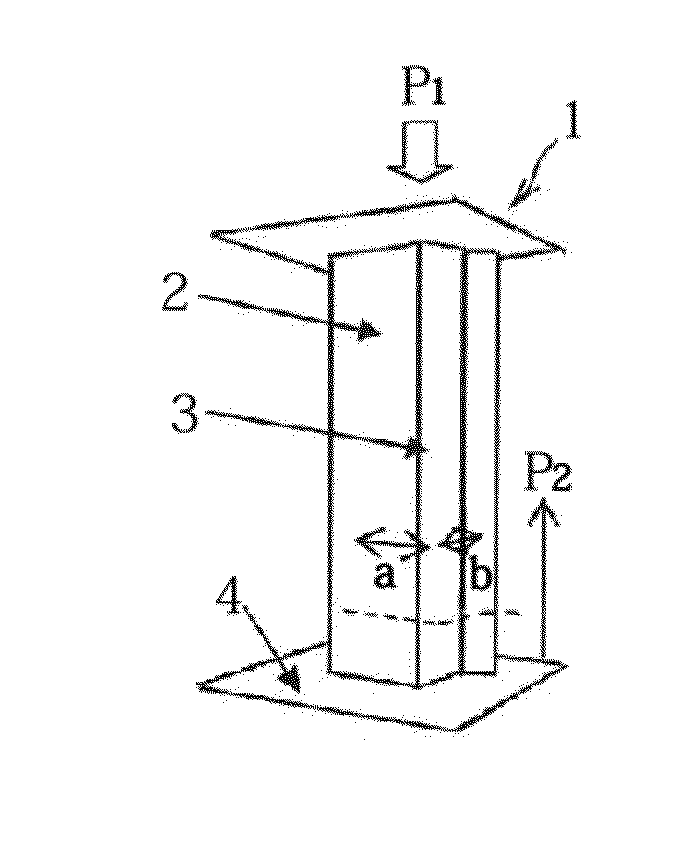
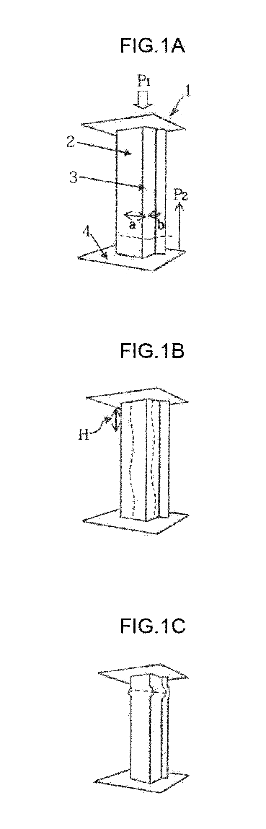
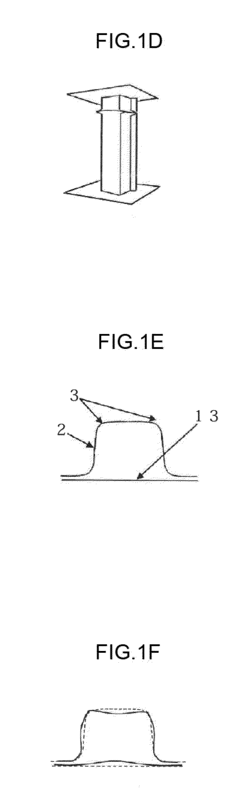
[0078]The present exemplary embodiment is an impact absorbing component that absorbs impact energy when impact load is exerted onto the component at one end portion in the impact absorption direction. The impact absorbing component is configured including a member formed into a profile including at least two ridge lines, by working a laminated metal sheet of uniform cross-section configured by lamination bonding sheet metal onto both faces of a core layer having appropriate Young's modulus and density. In the present specification, in cases in which an impact absorbing component has straight line portions in the profiles of cross-sections orthogonal to an impact absorption direction of the impact absorbing component, a ridge line is a line connecting the angled portions (having an angle of over 0° but less than 180°) formed between the straight line portions along the impact absorption direction (see the ridge line 3 in FIG. 1).

[0079]As illustrated in FIG. 3, a laminated metal sheet...

first examples

[0147]Explanation regarding the invention follows, based on specific examples and comparative examples.

[0148]Configuration of Employed Laminated Metal Sheet and Manufacturing Method

[0149]Laminated metal sheets configured with the surface layers and the core layers listed in Table 1 were manufactured as examples and comparative examples of the present invention. Bonding between the surface layers and the core layer was achieved using a structural adhesive (base: epoxy resin, coating amount 200 g / m2), an instant adhesive (base: cyanoacrylate, coating amount 200 g / m2), brazing filler metal (Sn—Pb based low temperature braze, melting point 183° C., usage amount 15 g / m2).

TABLE 1Configuration ofSurface LayersCore LayerLaminatedLaminatedThicknessThicknessMetal SheetMetal SheetSubstance(mm)Substance(mm)Ec / Eftc / tfAAl Killed0.3Wire Mesh1.45.5 × 10−24.7SteelBAl Sheet0.3Polyester1.45.5 × 10−24.7CAl Killed0.3Polypropylene1.43.2 × 10−34.7SteelDAl Killed0.3Wire Mesh3.15.5 × 10−210.4SteelEAl Killed...

second exemplary embodiment

Summary

[0190]The impact absorbing components according to the present exemplary embodiment are configured from a member formed by working a laminated metal sheet of uniform cross-section configured by lamination bonding surface layers made from a metal sheet having a higher Young's modulus than that of a core layer onto both faces of the core layer, with a sheet thickness ratio (tc / tf) of the sheet thickness of the core layer (tc) to the sheet thickness of the surface layers (tf) of the laminated metal sheet of from 2.0 to 7.0. Such an impact absorbing component has high impact energy absorption efficiency and is able to achieve a large weight reduction even though it has a simple profile.

[0191]Specifically, the bucking wavelength can be made shorter by making the sheet thickness ratio (tc / tf) of the sheet thickness of the core layer (tc) to the sheet thickness of the surface layers (tf) of the laminated metal sheet from 2.0 to 7.0. Thus the impact absorbing component formed from a ...


PUM


Abstract

The invention provides an impact absorbing component capable of stable bellows-shaped crushing deformation irrespective of the direction an impact load is exerted in, with a short bucking wavelength and large buckling load. A laminated metal sheet (impact absorbing component) includes a member that is formed by working the laminated metal sheet, in which surface layers made from metal sheets having a higher Young's modulus and density than those of a core layer are laminated onto both faces of the core layer, into a profile including at least two ridge lines, and that configures 50% or more of the maximum peripheral length of component cross-sections, wherein a sheet thickness ratio (tc/tf) of the sheet thickness (tc) of the core layer to the sheet thickness (tf) of the surface layers is 10.0 or less.

Description

CROSS-REFERENCE TO RELATED APPLICATIONS[0001]This application is a national stage application of International Application No. PCT / JP2014 / 055343, filed Mar. 3, 2014, which is incorporated herein by reference in its entirety, and which claims priority to Japanese Patent Application No. 2013-042208, filed on Mar. 4, 2013.TECHNICAL FIELD[0002]The present invention relates to an impact absorbing component employed in a means of transport such as an automobile.BACKGROUND ART[0003]Transport related safety standards are increasing year after year, and protecting cabin occupants in the event of a collision has become of utmost importance, even when detrimental to the transport function. Therefore, application of high strength steel sheet to frames surrounding cabins is progressing with the objective of absorbing energy during a collision and alleviating the impact transmitted to inside the cabin, and improvements to collision safety are being achieved.[0004]Moreover, recently not only colli...

Claims


Application Information

Patent Timeline
Patent Type & Authority Applications(United States)
IPC IPC(8): F16F7/12B62D21/15
CPCB62D21/15F16F7/12
Inventor KOGA, ATSUOOHISHI, HIROSHI
Owner NIPPON STEEL CORP
Why Eureka
Try Eureka