
Trunnion door hinge

a trunnion door and hinge technology, applied in the field of trunnion door hinges, can solve the problems of cam parts that wear out rather quickly, trunnion door hinges, relatively rapid wear and tear of cam parts, etc., and achieve the effect of less susceptible to wear and tear

Inactive Publication Date: 2016-01-21
HARRYVAN HLDG
View PDF20 Cites 10 Cited by
  • Summary
  • Abstract
  • Description
  • Claims
  • Application Information

AI Technical Summary

Benefits of technology

The present invention provides a trunnion door hinge that is less susceptible to wear and tear. The hinge has a stepped mechanism of cam parts that prevents point loads and counteracts wear and tear of cam parts. The hinge also has a braking mechanism for slowing down the hingeing, which offers additional design possibilities and design freedoms for the realization of trunnion doors with improved user-friendliness. The braking force is variable in dependence of the relative hinge angle between the first hinge part and the second hinge part.

Problems solved by technology

The point loads, which are occurring then, cause the cam parts to wear out rather rapidly.
This still leads to relatively rapid wear and tear of the cam parts.
A second drawback of the trunnion door hinges known from NL 2002119 has to do with the user-friendliness of the mounted trunnion door hinges.
Such kinds of behavior of trunnion doors provided with trunnion door hinges known from NL 2002119 usually are experienced by users as undesirable.

Method used


Image

  • Trunnion door hinge
  • Trunnion door hinge
  • Trunnion door hinge

Examples


Embodiment Construction

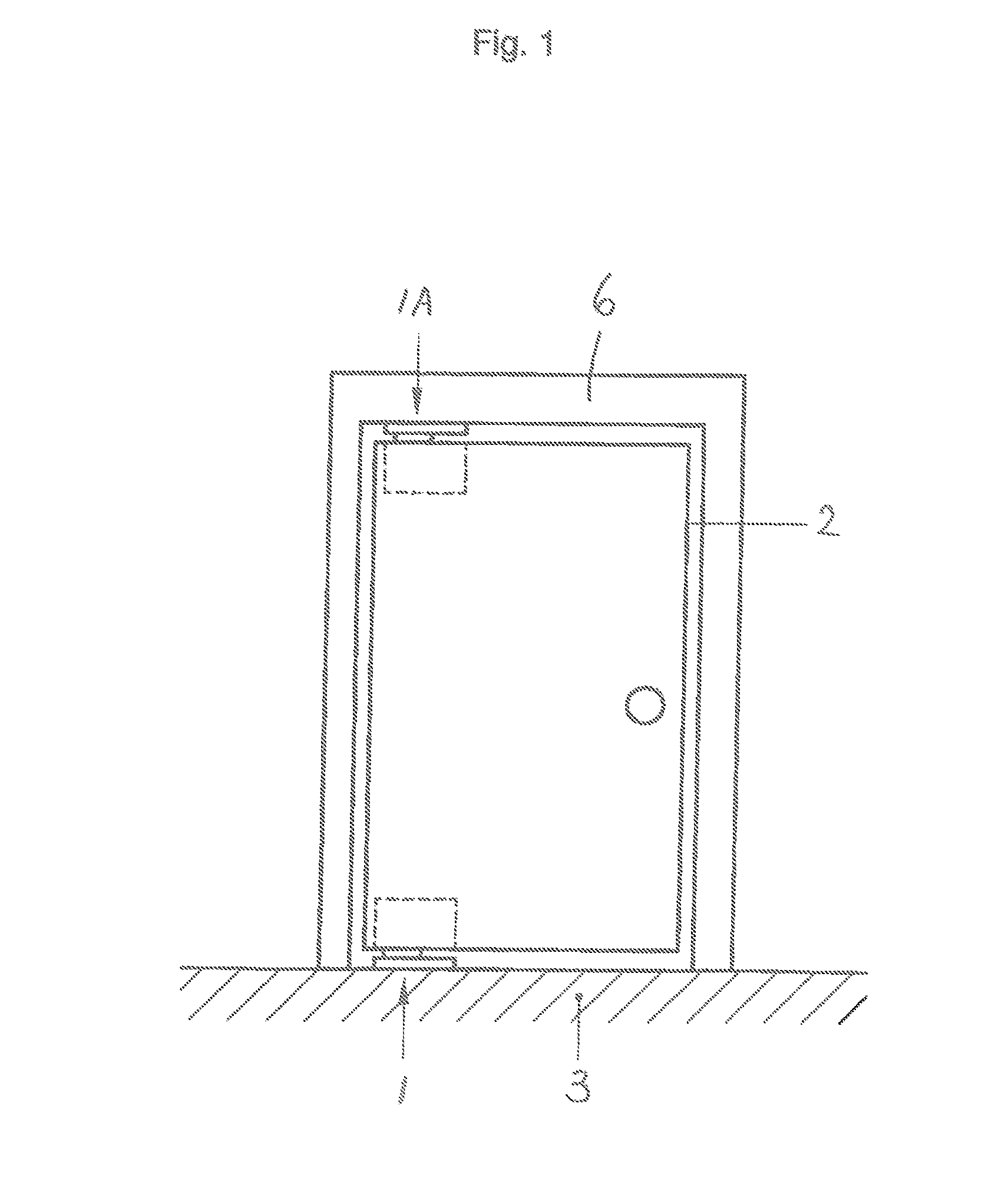
[0035]FIG. 1 shows a trunnion door 2 and, near to the door, a boundary of the doorway. The horizontal parts of said boundary are shown in the form of a floor 3 and an upper part 6 of a door frame. The trunnion door 2 is provided with two similar trunnion door hinges 1 and 1A according to the invention, the lower trunnion door hinge 1 of which is shown in greater detail in FIGS. 2-12. It is remarked that the trunnion door instead of two trunnion door hinges according to the invention may also have only one such trunnion door hinge, for example only at the bottom side or only at the top side of the trunnion door. The other hinge may then be of another type.

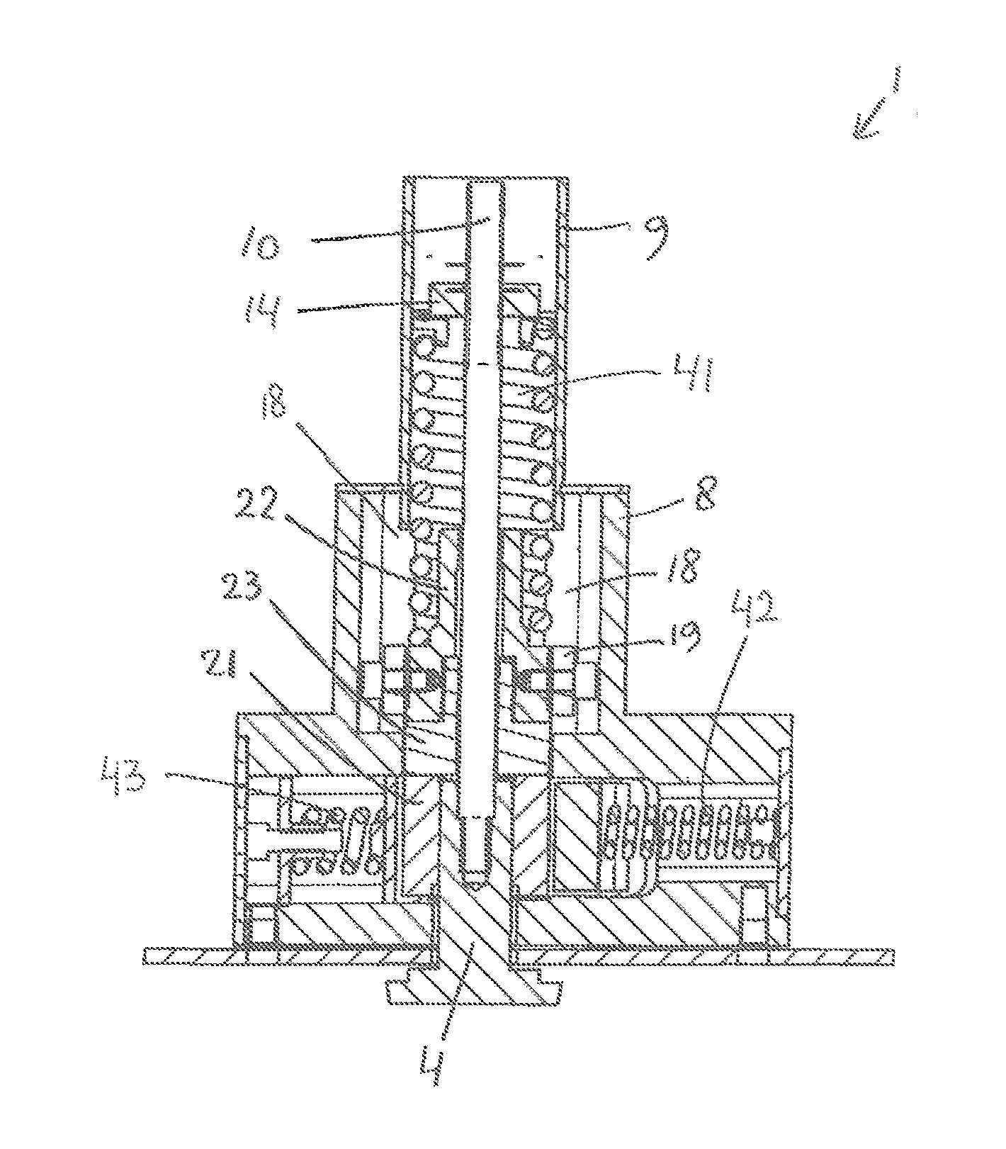
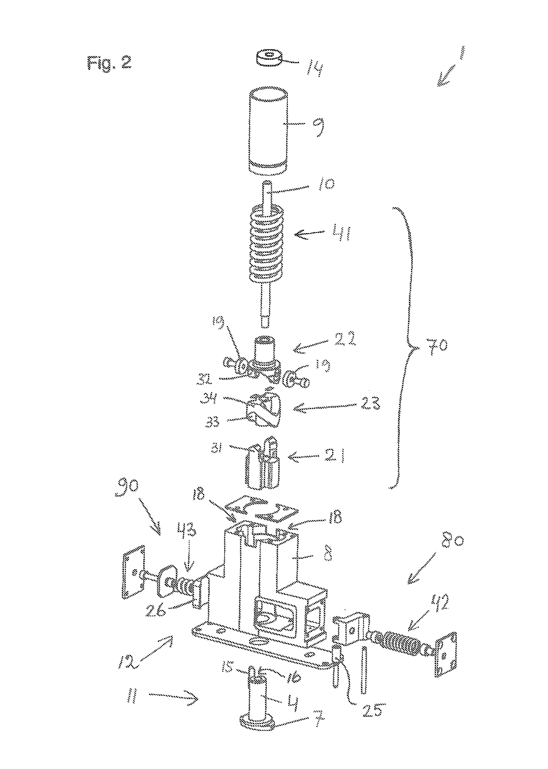
[0036]In FIG. 2 a number of parts and aspects of the shown trunnion door hinge according to the invention are indicated by reference numerals. The trunnion door hinge is indicated by reference numeral 1, the hinge shaft by No. 4, the first hinge part by No. 11, the second hinge part by No. 12, and the cam mechanism by No. 70. Of the...


PUM


Abstract

A trunnion door hinge having a first hinge part, a second hinge part and a cam mechanism. The cam mechanism has a first cam part, which is nonpivotable relative to the first hinge part, a second cam part, which is nonpivotable relative to the second hinge part, and a first spring element which presses the first cam part and the second cam part towards one another. The cam mechanism further has a third cam part in-between the first cam part and the second cam part. The third cam part at one end interlocks with the first cam part, and at the other end with the second cam part. During the hinging, the third cam part is helically pivotable relative to the first and the second cam part in a first and a second pivot range, respectively.

Description

FIELD OF THE INVENTION[0001]The invention relates to a trunnion door hinge for hingeably interconnecting a trunnion door and a horizontal boundary, situated near to the door, of the doorway.BACKGROUND OF THE INVENTION[0002]Because trunnion door hinges are mounted at the lower side and / or at the upper side of a door, they enable a relatively large hinging range. Doors provided with such hinges are sometimes referred to as trunnion doors. Some trunnion door hinges comprise an, often hydraulic, preferred positions mechanism for pushing the trunnion door in certain preferential hinging positions. This way, a user can easily swing the trunnion door into a number of discrete preferential hinging positions, for example a closed position or open position. In these preferential hinging positions an extra force is needed to move the hinge out of the preferential hinging position, as compared with the force needed to move the hinge in-between two such preferential hinging positions. Once a tru...

Claims


Application Information

Patent Timeline
Patent Type & Authority Applications(United States)
IPC IPC(8): E05D7/081
CPCE05D7/081E05D7/08E05D11/082E05F1/063E05F1/1223E05F5/00E05D11/105
Inventor PETRELLI, MARCUS, CORNELIS
Owner HARRYVAN HLDG
Learn More