Magnetically Secured Charging Devices

a charging device and magnetic technology, applied in the direction of charging stations, electric vehicle charging technology, transportation and packaging, etc., can solve the problems of wear and tear of cables, high cost of automatic alignment systems, and rapid depletion of fossil fuels

Pending Publication Date: 2020-04-16
MCCOLL STUART FRAZER
View PDF0 Cites 1 Cited by
  • Summary
  • Abstract
  • Description
  • Claims
  • Application Information

AI Technical Summary

Problems solved by technology

However, increased consumption of fossil fuels in recent years has rapidly depleted fossil fuels.
However, such automatic alignment systems are expensive, fragile, and complicated.
An additional critical component of the standard and state of the art is safety involving handling of high voltage as the cable from the electrical supply point usually lies on a pavement and is exposed to dust, heat and moisture, resulting in wear and tear of the cable.
Further, the wear and tear of cable may result in electrical shocks to a user when the user is exposed to a bare cable.
Though wireless charging devices are available in the market for charging electronic devices, wireless charging device for large vehicles such as electric cars are rarely reported.

Method used


Image

  • Magnetically Secured Charging Devices
  • Magnetically Secured Charging Devices
  • Magnetically Secured Charging Devices

Examples


Embodiment Construction

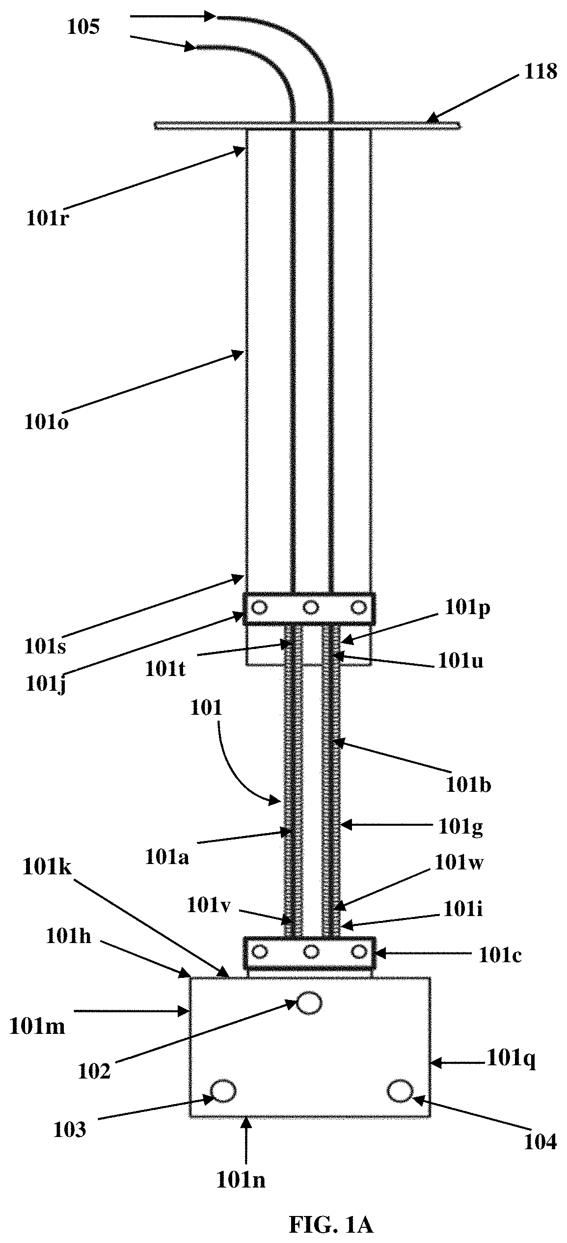
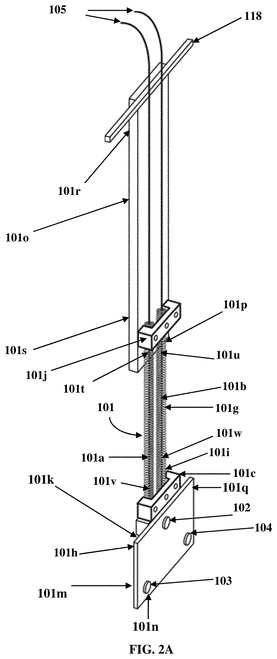
[0025]FIG. 1A illustrates a front elevation view of an electrical supply connector device 101 with a flexible support member 101g comprising a first spring member 101a and a second spring member 101b located along a length of the flexible support member 101g. In an embodiment, the flexible support member 101g is a combination of the first spring member 101a and the second spring member 101b.

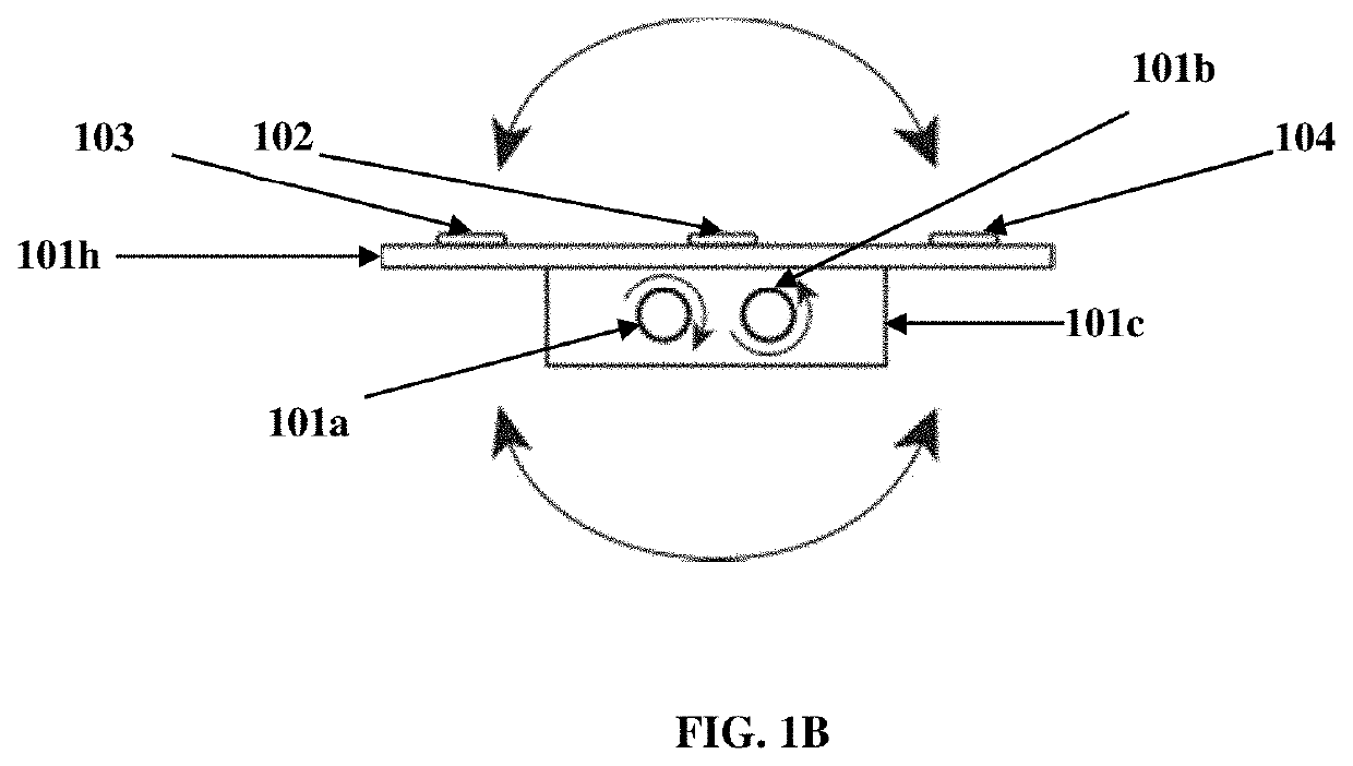
[0026]In an embodiment, the electrical supply connector device 101 comprises a flexible support member 101g and a supply connector frame 101h connected to a lower end 101i of the flexible support member 101g. The supply connector frame 101h comprises magnetic nodes 102, 103, and 104. The magnetic nodes 102, 103, and 104 are configured to be connected to an electrical power supply 105. For example, the magnetic nodes 102, 103, and 104 are configured to be connected to the electrical power supply 105 through a supply relay circuit 501, as exemplarily illustrated in FIG. 5A. For example, the magnet...


PUM


Abstract

An electrical supply connector device is provided. The electrical supply connector device comprises a flexible support member and a supply connector frame connected to a lower end of the flexible support member. The supply connector frame comprises a plurality of magnetic nodes that are connected to an electrical power supply. An electrical receiving connector device is also provided. The electrical receiving connector device comprises a receiving connector frame and magnetic nodes attached to the receiving connector frame.

Description

CROSS-REFERENCE TO RELATED APPLICATIONS[0001]This application claims priority to and the benefit of provisional patent application titled “AUTOMATIC CONNECTION DEVICE” application No. 62 / 571,242, filed in the United States Patent Office on Oct. 11, 2017, provisional patent application titled “QUICK ELECTRIC CONNECT / DISCONNECT DEVICE” application No. 62 / 578,662, filed in the United States Patent Office on Oct. 30, 2017, and provisional patent application titled “AUTOMATIC EV CHARGING CONNECTION III” application No. 62 / 626,203 filed in the United States Patent Office on Feb. 5, 2018. The specifications of the above referenced patent applications are incorporated herein by reference in their entirety.BACKGROUND[0002]For thousands of years, people have relied on traditional fossil fuels such as petroleum, coal and other mineral resources as a source of power. The utilization of fossil fuels has enabled large-scale industrial development. However, increased consumption of fossil fuels in...

Claims


Application Information

Patent Timeline
Patent Type & Authority Applications(United States)
IPC IPC(8): B60L53/16H01R11/30
CPCH01R11/30B60L53/16B60L53/35B60L53/62Y02T10/70Y02T10/7072Y02T90/12Y02T90/14
Inventor MCCOLL, STUART FRAZER
Owner MCCOLL STUART FRAZER
Why Eureka
Try Eureka