Drilling apparatus

a drilling apparatus and drill string technology, applied in drilling rods, drilling pipes, cutting machines, etc., can solve the problems of reducing increasing the wear and erosion of the bit shank and/or the turbine shaft, and increasing the length of the turbine-drill bit assembly with the reduction of the rigidity of the drill string, so as to achieve more rigid and stable, less vibration, and higher directional drilling performance

Inactive Publication Date: 2015-09-03
HALLIBURTON ENERGY SERVICES INC
View PDF1 Cites 1 Cited by
  • Summary
  • Abstract
  • Description
  • Claims
  • Application Information

AI Technical Summary

Benefits of technology

[0009]It is therefore an object of the present invention to provide an improved tandem turbine-drill bit assembly that is more rigid and more stable and suffers from fewer vibrations allowing higher directional drilling performance.

Problems solved by technology

As mentioned above, due to the types of connections provided on bit shanks and turbine shafts, when assembled in tandem, there may be a substantial gap between the turbine stabiliser and the gauge end or sleeve end of the bit.
Such a gap allows rings of rock debris and mud resulting from the drilling operation, to form around the turbine shaft and bit shank thereby increasing wear and erosion of the bit shank and / or the turbine shaft.
Another drawback of the gap results in a longer length of the turbine-drill bit assembly with reduced rigidity of the drill string.
This longer length may also create an instability of the drill bit and vibrations that effectively reduce the drilling efficiency.
This is particularly a problem in eccentric turbine-drill bit assemblies or in directional drilling.

Method used


Image

  • Drilling apparatus
  • Drilling apparatus
  • Drilling apparatus

Examples


Embodiment Construction

[0027]The present invention will be described with respect to particular embodiments and with reference to certain drawings but the invention is not limited thereto. The drawings described are only schematic and are non-limiting. In the drawings, the size of some of the elements may be exaggerated and not drawn on scale for illustrative purposes.

[0028]It will be understood that the terms “vertical” and “horizontal” are used herein refer to particular orientations of the Figures and these terms are not limitations to the specific embodiments described herein.

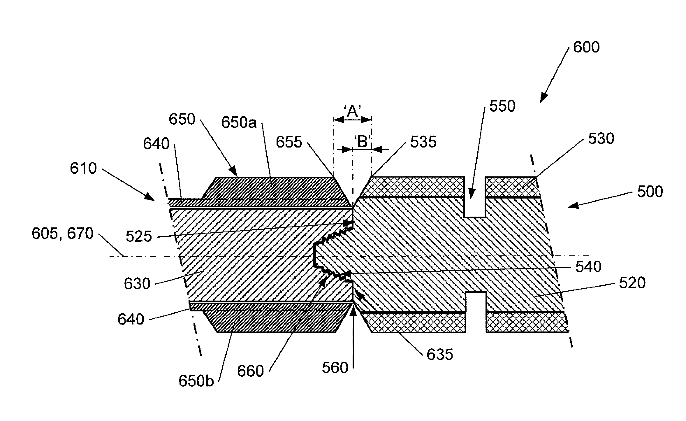
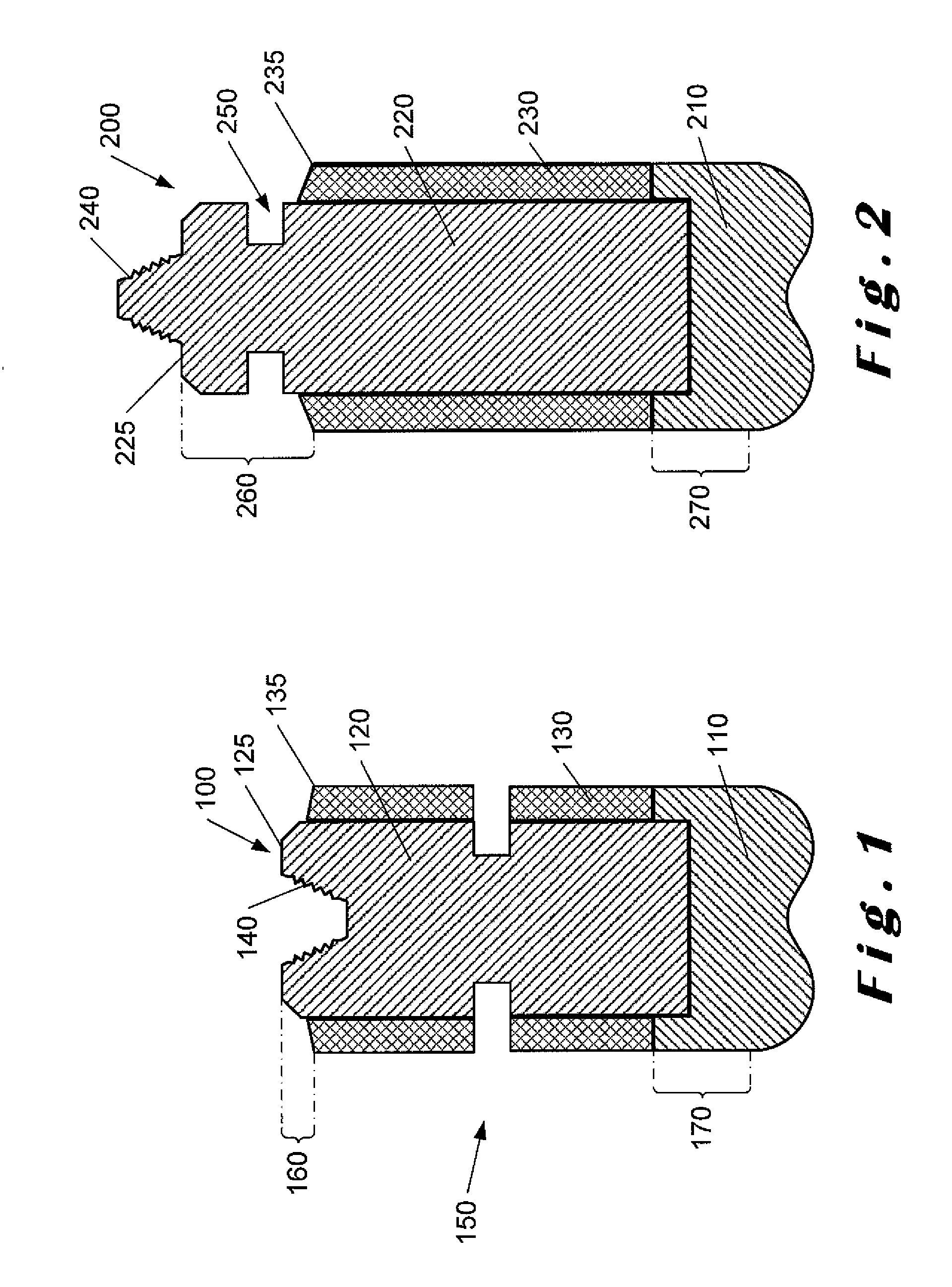
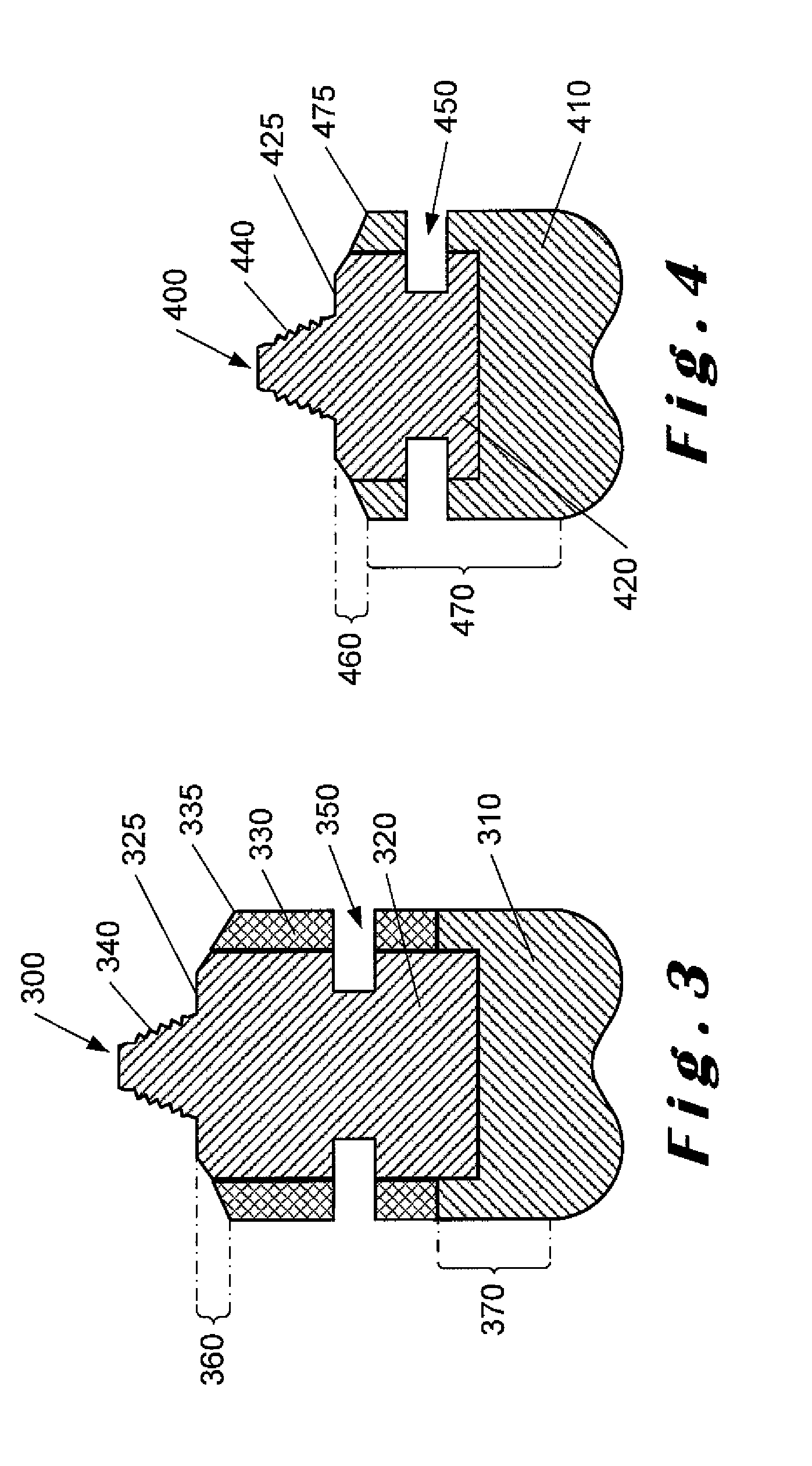
[0029]As used herein, the terms “box” and “pin” refer to the type of connection provided on the turbine shaft and / or the bit shank, and the terms “connector” or “connection” are implied.

[0030]Each drill bit comprises a bit head and at least a bit gauge. Typically, each drill bit can be considered to comprise a bit head, a bit gauge and a bit shank. In addition, a drill bit may also comprise a bit sleeve. The bit gauge is typicall...


PUM


Abstract

Described herein is a turbine-drill bit assembly (600) in which the gap between the turbine and the drill bit is minimised and overall assembly is substantially shorter. The assembly (600) comprises a box connection turbine (610) connected to a pin connection drill bit (500). The turbine (610) has a turbine body (640, 650, 650a, 650b) around a turbine shaft (630), the turbine body (640, 650, 650a, 650b) having a turbine stabiliser (650, 650a, 650b). The drill bit (500) has a bit gauge or a bit sleeve (530) around a bit shank (520), an end (655) of the turbine stabiliser (650) nearest the drill bit (500) being spaced a first maximum distance (A) from an end (535) of the bit gauge or bit sleeve (530). In addition, a shouldering interface (560) is formed at respective abutment shouldering surfaces (635, 525) of the turbine shaft (630) and bit shank (520) when the drill bit (500) is attached to the turbine shaft (630), the interface (560) being spaced a second maximum distance (B) from an end (535) of the bit gauge or bit sleeve (530). The advantage of these limited distances reduces the annular volume in which mud and rock debris can build up thereby reducing erosion and wear, In addition, a more rigid assembly is provided which is less susceptible to vibrations. This reduces the risk of sticking of the turbine-drill bit assembly in the wellbore and provides better directional control.

Description

FIELD OF THE INVENTION[0001]The present invention relates to improvements in or relating to drilling apparatus, and is more particularly concerned with tandem turbine and drill bit arrangements.BACKGROUND TO THE INVENTION[0002]It is known to use down-hole turbines in drill strings in tandem with drill bits. A performance turbine is used in drilling operations to provide higher power and rotational speed to the drill bit. The turbine comprises a turbine body and a turbine shaft, the turbine shaft rotation being independent from the turbine body. The turbine body is connected to the drill string rotating at the drill string speed. The turbine stabiliser may be mounted on a turbine body surrounding the turbine shaft. The turbine body may comprise the turbine stabiliser. The turbine shaft is driven by mud flowing through the turbine and rotates at a higher rotational speed independently of the drill string.[0003]As described above, the performance turbine is connected to the drill strin...

Claims


Application Information

Patent Timeline
Patent Type & Authority Applications(United States)
IPC IPC(8): E21B4/02E21B17/10E21B10/00
CPCE21B4/02E21B17/1092E21B17/1078E21B10/00
Inventor DA SILVA, NUNODUPONT, OLIVIER
Owner HALLIBURTON ENERGY SERVICES INC
Why Eureka
Try Eureka