Soft Switching on all switching elements Converter through Current Shaping "Bucharest Converter"

a technology of switching elements and converters, applied in the direction of electric variable regulation, process and machine control, instruments, etc., can solve the problems of increasing conduction losses in primary and secondary

Inactive Publication Date: 2016-01-21
ROMPOWER TECH HLDG LLC
View PDF7 Cites 20 Cited by
  • Summary
  • Abstract
  • Description
  • Claims
  • Application Information

AI Technical Summary

Benefits of technology

[0003]In both previous applications is obtained soft switching in the secondary and the primary. In one of the claims in “Soft Switching on all Switching Elements Two Transistors Forward Converter” patent application (Exhibit A), a current source is injected at the node where the synchronous rectifiers and output choke connect with the purpose to address the current need of the output choke and the additional current injected to reverse the current flow through SR2, FIG. 8 of Exhibit A. Once the current through SR2 is reversed the SR2 is turned off and the negative current is transferred to the primary to discharge the parasitic capacitance of the primary switches to zero and create zero voltage turn on conditions for the primary switching elements. The current injection is done for a very short time prior the primary switches turns on. The current injection can be rectangular, trapezoidal, triangular, half sinusoidal or any other shape as long as it is narrow and has the proper amplitude. The goal is to overwhelm the current demanded by the output choke for a short time period prior the primary switches turn off. This can be thought as a method of disconnecting the output choke from the rectifier means for a very short period of time and forcing the SR2 to turn off at zero or a controlled small negative current.

Problems solved by technology

The method does work well for lighter loads but for very high currents the magnetizing current has to be increased to very high levels which will increase the conduction losses in the primary and secondary.

Method used


Image

  • Soft Switching on all switching elements Converter through Current Shaping "Bucharest Converter"
  • Soft Switching on all switching elements Converter through Current Shaping "Bucharest Converter"
  • Soft Switching on all switching elements Converter through Current Shaping "Bucharest Converter"

Examples


Embodiment Construction

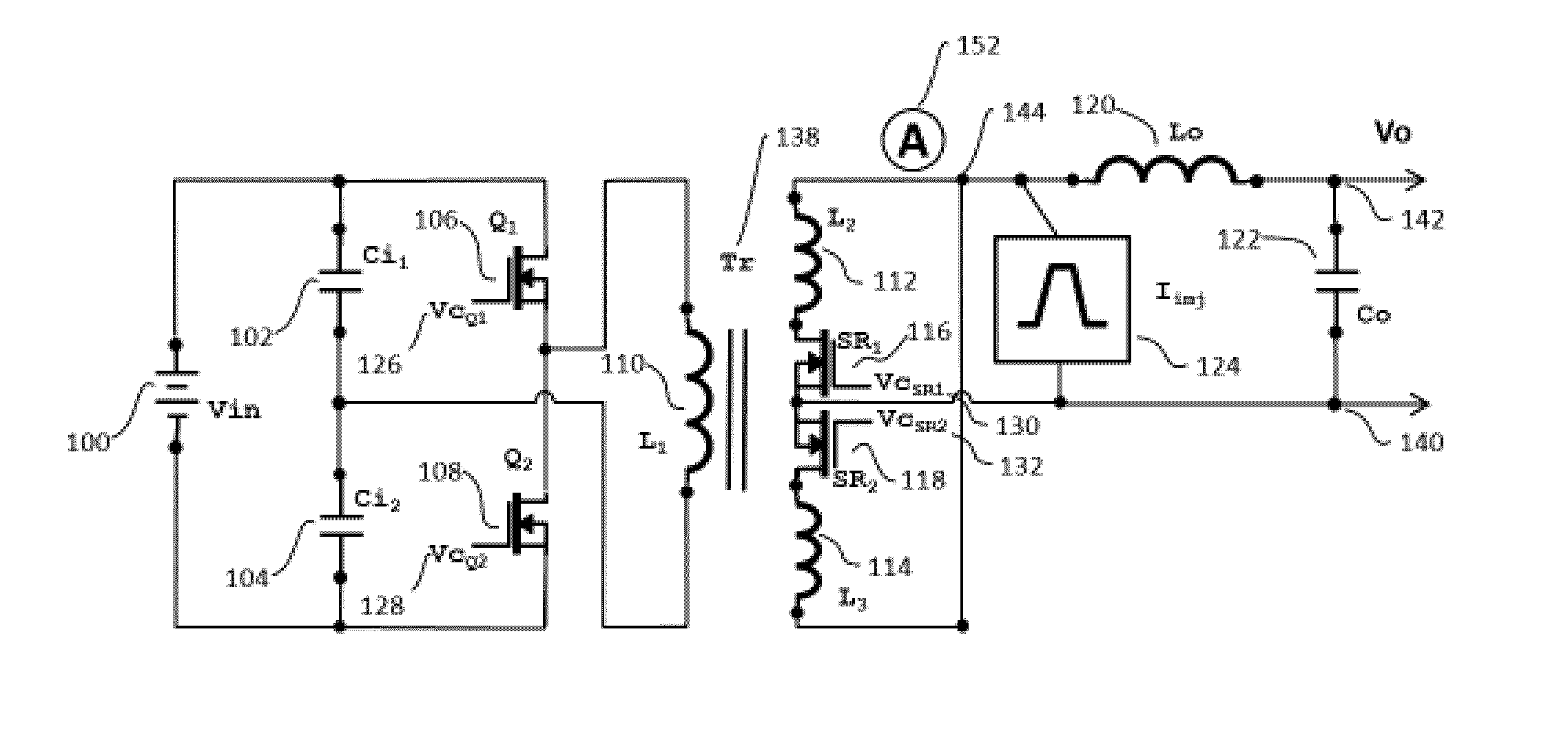
[0023]The concepts of the present invention comprises injecting a very narrow shaped current with an amplitude larger than the current flowing through the output choke by a controlled amount just before the primary switches will turn on by a determined amount of time in advance. The additional conduction losses associated by the current injection is designed to be much lower than the conduction losses associated by an increase level of the magnetizing current in order to exceed the output current. For that reason the current source which is used for current injection has to produce a narrow and high amplitude current shape. In this patent application we present several methods to create such a current shape. To maintain a good efficiency of the converter over the entire loading conditions the amplitude of the current injection has to be modulated proportional with the output current.

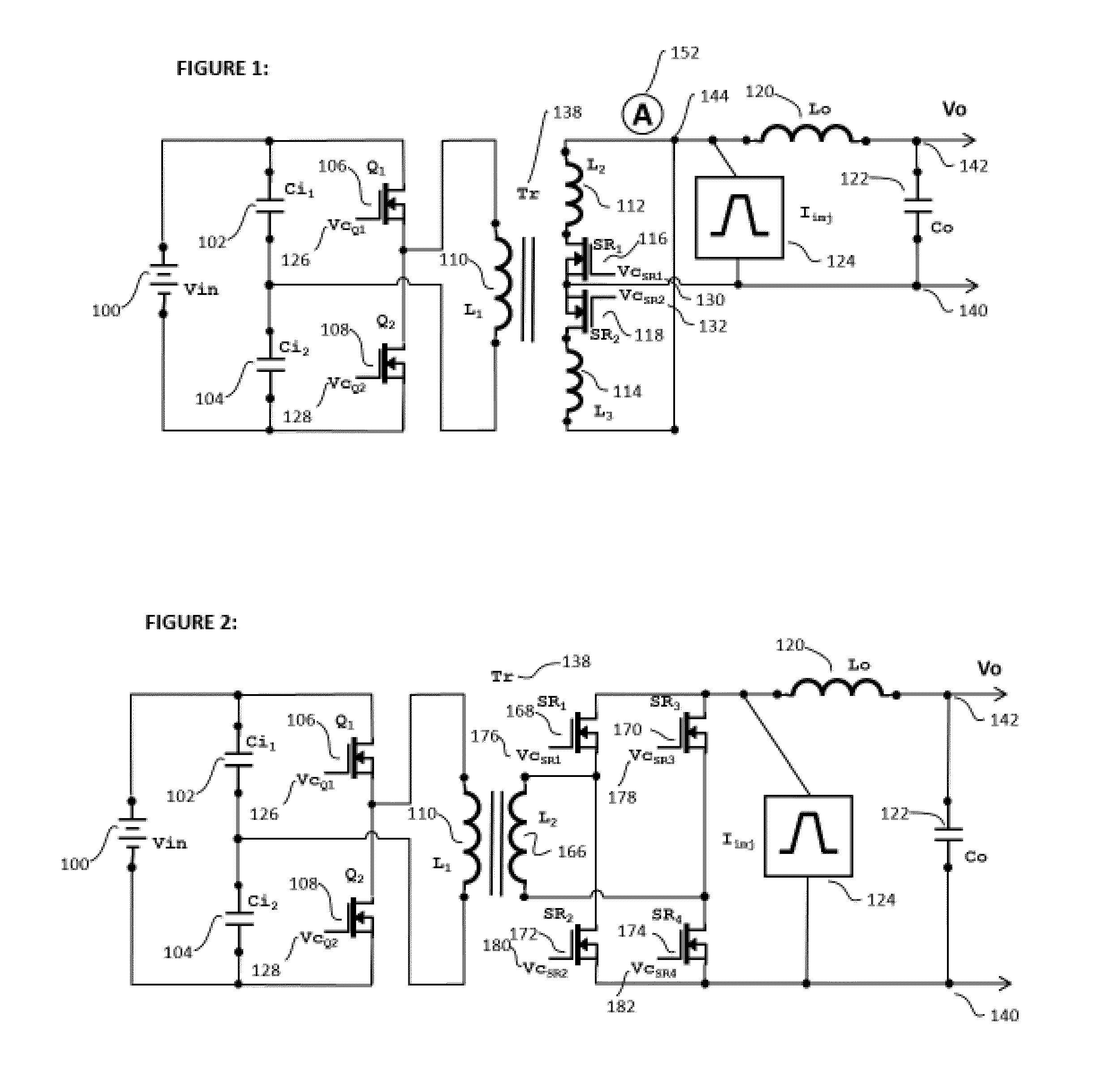
[0024]In FIG. 1 is presented a half bridge topology using the transformer, Tr, 138, with a primary wi...


PUM


Abstract

A method is shown to create soft transition in selected topologies by controlling and designing a current pulse injection in front of the output choke to overwhelm the output current at a certain point in the switching cycle.

Description

RELATED APPLICATION / CLAIM OF PRIORITY[0001]This application is related to and claims priority from U.S. provisional application Ser. No. 62 / 023,025, filed Jul. 10, 2014, which provisional application is incorporated by reference herein.1. INTRODUCTION[0002]The present invention further develops original concepts that have been described in two previous applications, one entitled “Soft Switching on all Switching Elements Two Transistors Forward Converter” PCT patent application serial number PCT / US14 / 37736, filed May 12, 2014 and the other entitled “Soft Switching Converter by Steering the Magnetizing Current”, U.S. patent application Ser. No. 14 / 274,701, filed May 10, 2014, copes of which are attached as Exhibit A and Exhibit B, respectively, and each of those applications is incorporated by reference herein.[0003]In both previous applications is obtained soft switching in the secondary and the primary. In one of the claims in “Soft Switching on all Switching Elements Two Transistor...

Claims


Application Information

Patent Timeline
Patent Type & Authority Applications(United States)
IPC IPC(8): H02M3/335
CPCH02M3/33546H02M3/33576H02M1/0058Y02B70/10
Inventor JITARU, IONEL
Owner ROMPOWER TECH HLDG LLC
Why Eureka
Try Eureka