Crusher belt tensioning apparatus

a belt tensioning and belt technology, applied in the field of belt tensioning equipment, can solve the problems of high belt and bearing temperature, large tensioning device, and disadvantages of conventional belt tensioning devices, and achieve the effect of dissolving vibration and distortion forces and eliminating the transfer of loading forces

Inactive Publication Date: 2016-01-28
SANDVIK INTELLECTUAL PROPERTY AB
View PDF12 Cites 8 Cited by
  • Summary
  • Abstract
  • Description
  • Claims
  • Application Information

AI Technical Summary

Benefits of technology

[0005]It is an objective of the present invention to provide a bell tensioning apparatus for a crusher and in particular a mobile crushing unit that is effective to apply a varying degree of tension to the belt of a belt drive unit extending between a drive motor and the crusher. It is a further objective to provide a belt tensioning assembly that is adjustable via a convenient action by service personnel. It is a further objective to provide a belt tensioning assembly configured to dissipate vibration and distortion forces at the belt drive assembly. It is a yet further objective to minimise as far as possible and potentially eliminate the transfer of loading forces between a crusher drive shaft and a powered motor driven shaft.

Problems solved by technology

However, conventional belt tensioning devices are disadvantageous for a number of reasons.
In particular, where the tensioning device utilises a drum to contact an external facing side of the belt, it is common for the belt to misalign at the drum and to impart vibrations to the revolving bell resulting in high belt and bearing temperatures.
However, such tensioning devices are large and difficult to accommodate on a mobile crusher where available space at the chassis is limited.
Additionally, conventional shock absorbing spring arrangements are susceptible to accumulation of dirt causing them to crack to become coil bound preventing shock absorbing compression as intended.
A further problem exists with the mounting of tension pulleys that are susceptible to belt misalignment due to their mounting arrangement.
Additionally, conventional mountings for tension pulleys tend to be large and again difficult to accommodate at the mobile chassis frame.

Method used


Image

  • Crusher belt tensioning apparatus
  • Crusher belt tensioning apparatus
  • Crusher belt tensioning apparatus

Examples


Embodiment Construction

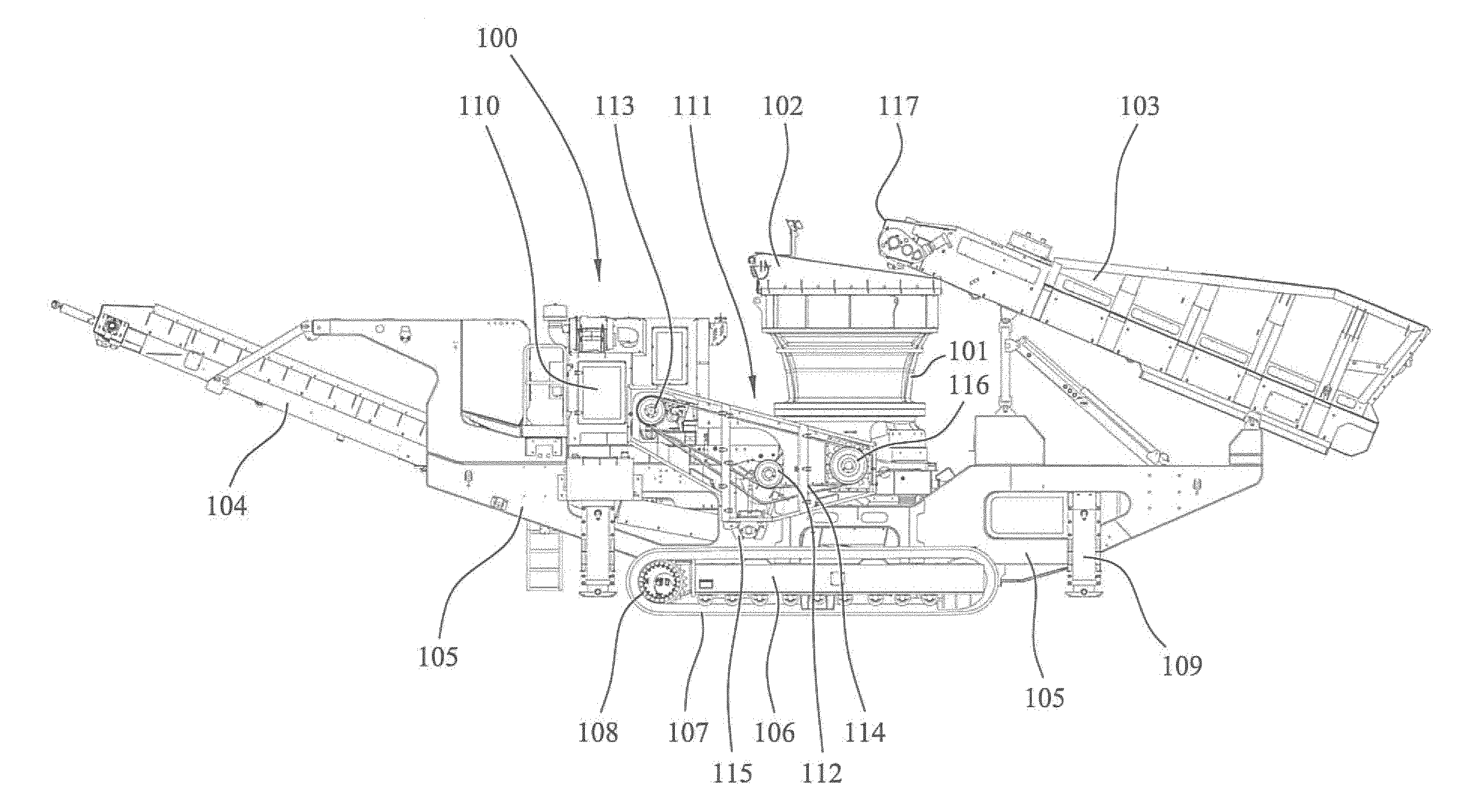
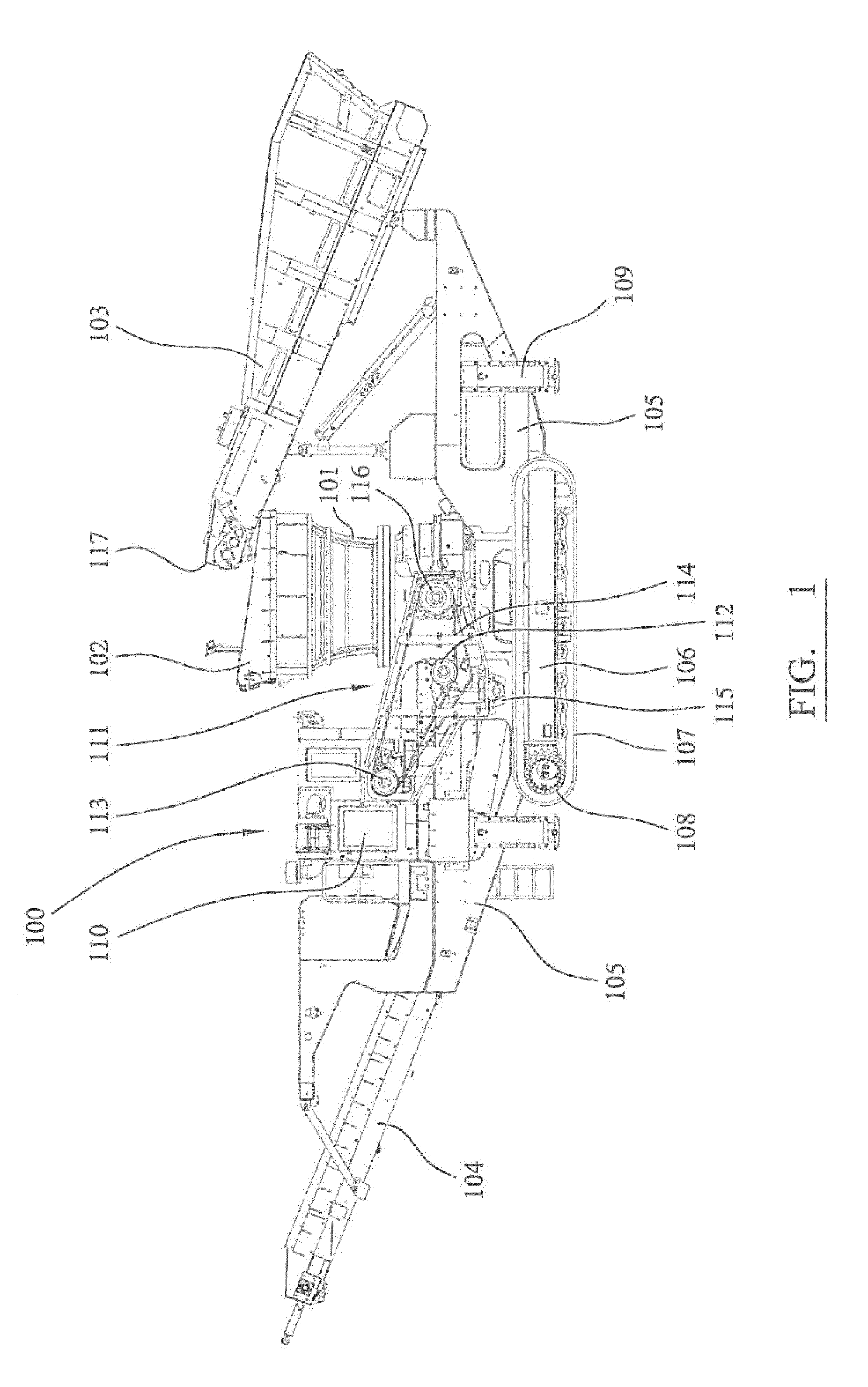
[0052]Referring to FIGS. 1 and 3, a mobile crushing plant 100 comprises a main frame 105 providing a central support for the operative components of the plant 100. A chassis 106 is mounted to a lower region of frame 105 that in turns mounts two sets of a plurality of wheels 108 around which extend respectively a continuous belt track 107. In particular, plant 100 comprises a pair of endless tracks 107 (and associated drive components) positioned laterally at each side of chassis 106 at the lower region of frame 105. Wheels 108 are driven by a power unit 110 so as to drive each belt 107 to propel plant 100 over the ground.

[0053]A plurality of stabilising legs 109 project downwardly from frame 105 and comprise hydraulic rams (not shown) for lowering into contact with the ground to help stabilise plant 100 during use. Frame 105 further supports a feed conveyor 103 having a discharge end 117 positioned vertically above a crusher 101 mounted substantially at frame 105 above chassis 106. ...


PUM


Abstract

A crusher belt tensioning apparatus for mounting at a crusher and in particular a mobile crushing unit is provided. The belt tensioning assembly includes a base frame that mounts a moveable swing arm via a plurality of non-rigid mountings to provide vibration and shock absorption during use. A variable belt tension setting is achieved via a linear actuator operating between the swing arm and the base frame to change the relative position of a tension pulley in contact with the drive belt.

Description

FIELD OF INVENTION[0001]The present invention relates to a crusher belt tensioning apparatus and in particular, although not exclusively, to a crusher processing unit having a belt coupling a drive shaft of a crusher and a separate drive shaft associated with a motor with a tensioning device forming a part of the drive assembly and configured to apply tension to the belt.BACKGROUND ART [0002]A variety of different crushers have evolved suitable for processing stone, minerals and both domestic and industrial waste including construction materials to generate smaller particulate material and aggregate for subsequent processing or disposal. Conventional crushers include gyratory, impact, vibration and jaw crushers. Typically, the crusher is provided with a hopper for receiving the bulk material and a discharge conveyor to transfer the processed and crushed material to a discharge location. In certain situations, a supply conveyor feeds the material to be processed into a crusher hopper...

Claims


Application Information

Patent Timeline
Patent Type & Authority Applications(United States)
IPC IPC(8): F16H7/12B02C21/02F16H7/08F16H25/20
CPCF16H7/1209B02C21/02F16H7/1281F16H2007/0842F16H25/2018F16H2007/0802F16H7/0829Y02W30/58
Inventor WHEATLEY, MARTINMURR, RICHARDTALBOT, SIAN
Owner SANDVIK INTELLECTUAL PROPERTY AB
Why Eureka
Try Eureka