System and method for monitoring optical subsystem performance in cloud lidar systems

a cloud lidar system and optical subsystem technology, applied in the field of optical components, can solve the problems of adding to the cost and complexity of the lidar system

Active Publication Date: 2016-01-28
ROSEMOUNT AEROSPACE
View PDF10 Cites 89 Cited by
  • Summary
  • Abstract
  • Description
  • Claims
  • Application Information

AI Technical Summary

Benefits of technology

[0012]A system for monitoring performance of optical components includes a laser and a plurality of optical components. A processor is operatively connected to a memory. The memory includes instructions recorded thereon that, when read by the p

Problems solved by technology

However, the inclusion of multiple additional photodetectors solely for

Method used


Image

  • System and method for monitoring optical subsystem performance in cloud lidar systems
  • System and method for monitoring optical subsystem performance in cloud lidar systems
  • System and method for monitoring optical subsystem performance in cloud lidar systems

Examples


Embodiment Construction

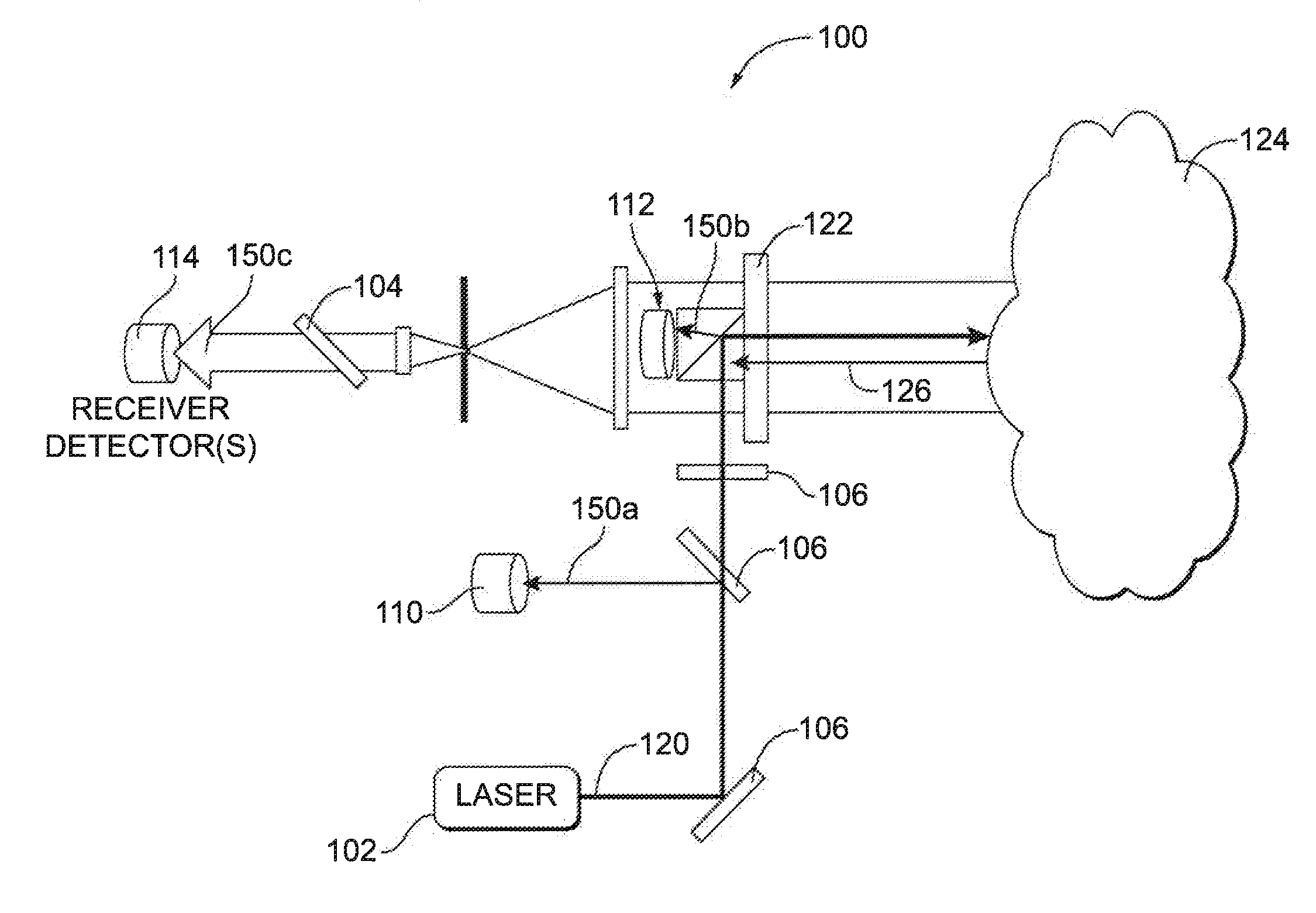
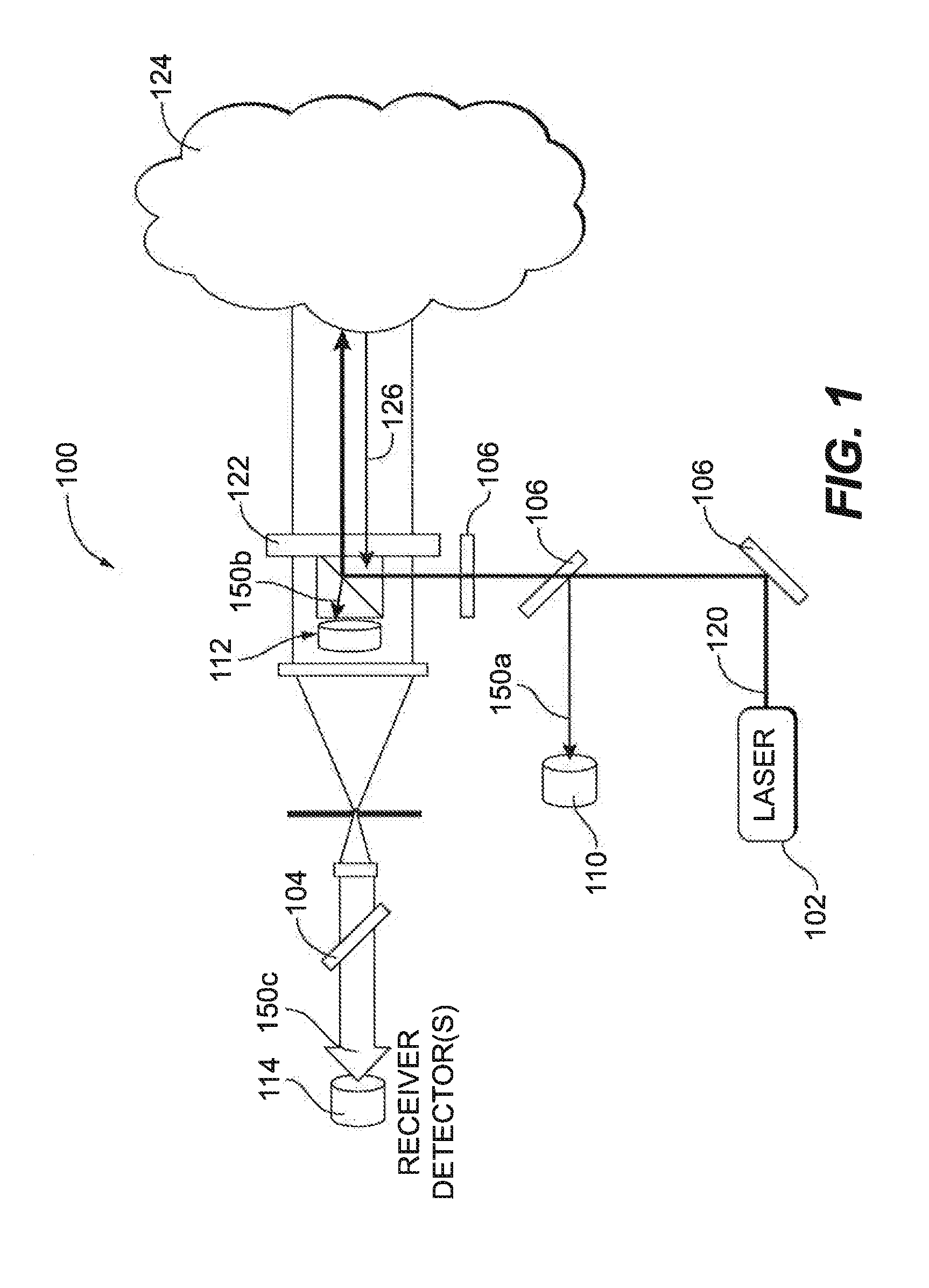
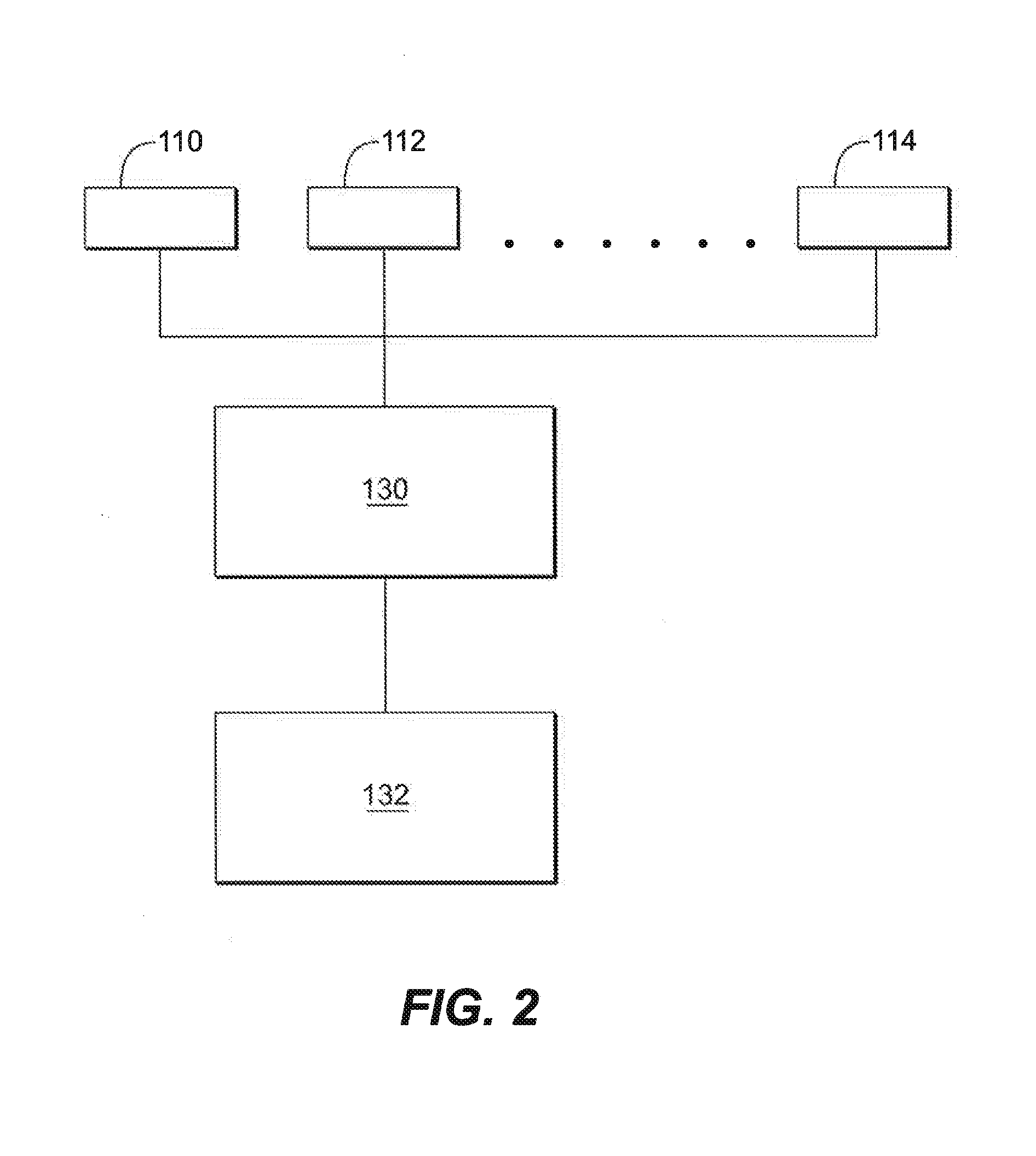
[0019]Reference will now be made to the drawings wherein like reference numerals identify similar structural features or aspects of the subject disclosure. For purposes of explanation and illustration, and not limitation, a partial view of an exemplary embodiment of a system and method for monitoring optical performance in accordance with the disclosure is shown in FIG. 1 and is designated generally by reference character 100. Other embodiments of systems and methods in accordance with the disclosure, or aspects thereof, are provided in FIGS. 2-4, as will be described.

[0020]FIG. 1 illustrates a LIDAR system 100 in accordance with the present disclosure for monitoring performance of optical components. System 100 includes a laser 102 and a plurality of optical components. As shown in FIG. 1, optical components include receiver optics 104, transmitter optics 106, photodetectors 110, 112, 114 and window 122. Photodetectors 110, 112, 114 include but are not limited to a trigger photodio...


PUM


Abstract

A method of detecting optical subsystem failures includes emitting a pulsed light beam from a laser through a window. A reflection signal indicative of a portion of the beam reflected by the window is compared to an expected signal to monitor for degradation of an optical component.

Description

BACKGROUND OF THE INVENTION[0001]1. Field of the Invention[0002]The present disclosure relates to optics, and more particularly to monitoring performance of optical components.[0003]2. Description of Related Art[0004]A cloud LIDAR system uses lasers and an optical transmitter subsystem to illuminate a portion of a cloud and an optical receiver coupled to a series of photodetectors to measure the reflected light. These measurements are then processed by onboard digital electronics to calculate cloud parameters. In a system such as this, it is beneficial to detect and report faults and / or performance degradation of the optical and electro-optical components, such as lasers, transmitter subsystems and photodetectors. Typical LIDAR systems require multiple additional photodetectors solely for the purpose of detecting failures.[0005]Such conventional methods and systems have generally been considered satisfactory for their intended purpose. However, the inclusion of multiple additional p...

Claims


Application Information

Patent Timeline
IPC IPC(8): G01S7/497G01M11/00
CPCG01M11/00G01S7/497G01S7/4972G01S17/95G01S2007/4975Y02A90/10
Inventor ANDERSON, KAARE J.RAY, MARK D.
Owner ROSEMOUNT AEROSPACE
Why Eureka
Try Eureka