Power system stabilization method, power system stabilization system, and power supply device

a power system and stabilization system technology, applied in the direction of instruments, computer control, process and machine control, etc., can solve the problem of not being able to execute control at the original desired control timing

Active Publication Date: 2016-01-28
PANASONIC CORP
View PDF1 Cites 36 Cited by
  • Summary
  • Abstract
  • Description
  • Claims
  • Application Information

AI Technical Summary

Benefits of technology

[0007]There is room for improvement of the front-loaded control in the control system described in Patent Literature 1.
[0008]In light of the above circumstances, a non-limiting and exemplary embodiment provides a power system stabilization method that is improved over the related art.
[0009]The additional benefits and superiority of the disclosed embodiment is clear from the specification and the drawings. The above benefits and / or superiority are each given by the features disclosed in the various embodiments, specification, and drawings. Furthermore, not all of the above features disclosed in the various embodiments, specification, and drawings are required to obtain one or more of the above benefits and / or superiority.
[0010]A power system stabilization method according to one aspect of the present disclosure is a power system stabilization method includes: receiving a power command value from a power control center that monitors a power system; transmitting the power command value to a power supply device; causing the power supply device to supply power to the power system according to the power command value; generating a prediction command value according to past power command values received from the power control center, the prediction command value being a prediction value of a power command value to be transmitted from the power control center next after the power command value; transmitting the prediction command value to a power supply device; causing the power supply device to supply power to the power system according to the power prediction command value; receiving the next power command value from the power control center; transmitting the next power command value to the power supply device.
[0011]According to the present disclosure, a power system stabilization method that is improved over the related art is realized.

Problems solved by technology

The power command value may be transmitted to the power supply device from the management device using an Internet link, for example, but in some cases a variable communication delay occurs between the management device and the power supply device, and it may not be possible to execute control at the originally desired control timings.

Method used


Image

  • Power system stabilization method, power system stabilization system, and power supply device
  • Power system stabilization method, power system stabilization system, and power supply device
  • Power system stabilization method, power system stabilization system, and power supply device

Examples


Embodiment Construction

Underlying Knowledge Forming Basis of the Present Disclosure

[0023]The inventors obtained the following findings as a result of diligent investigation.

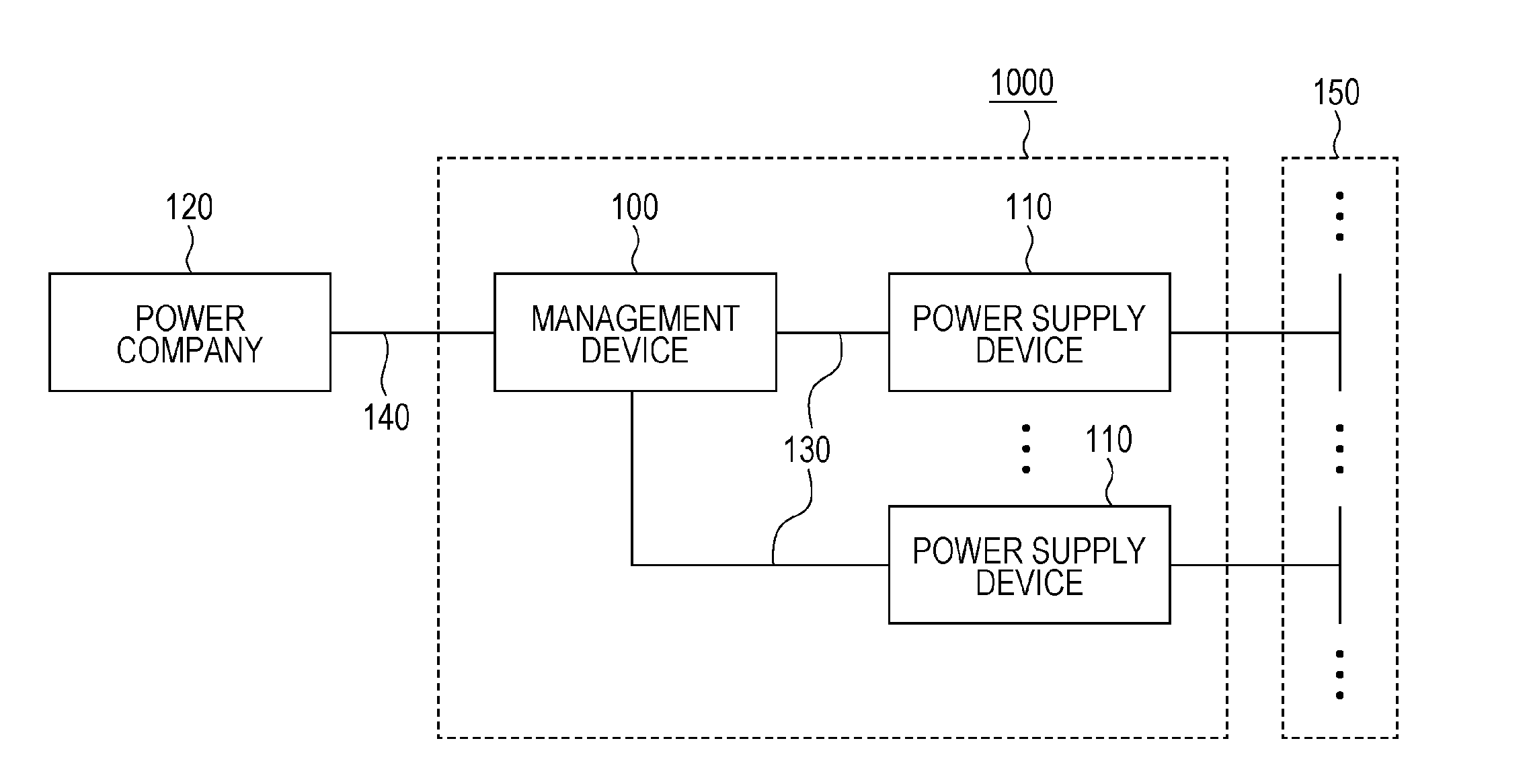
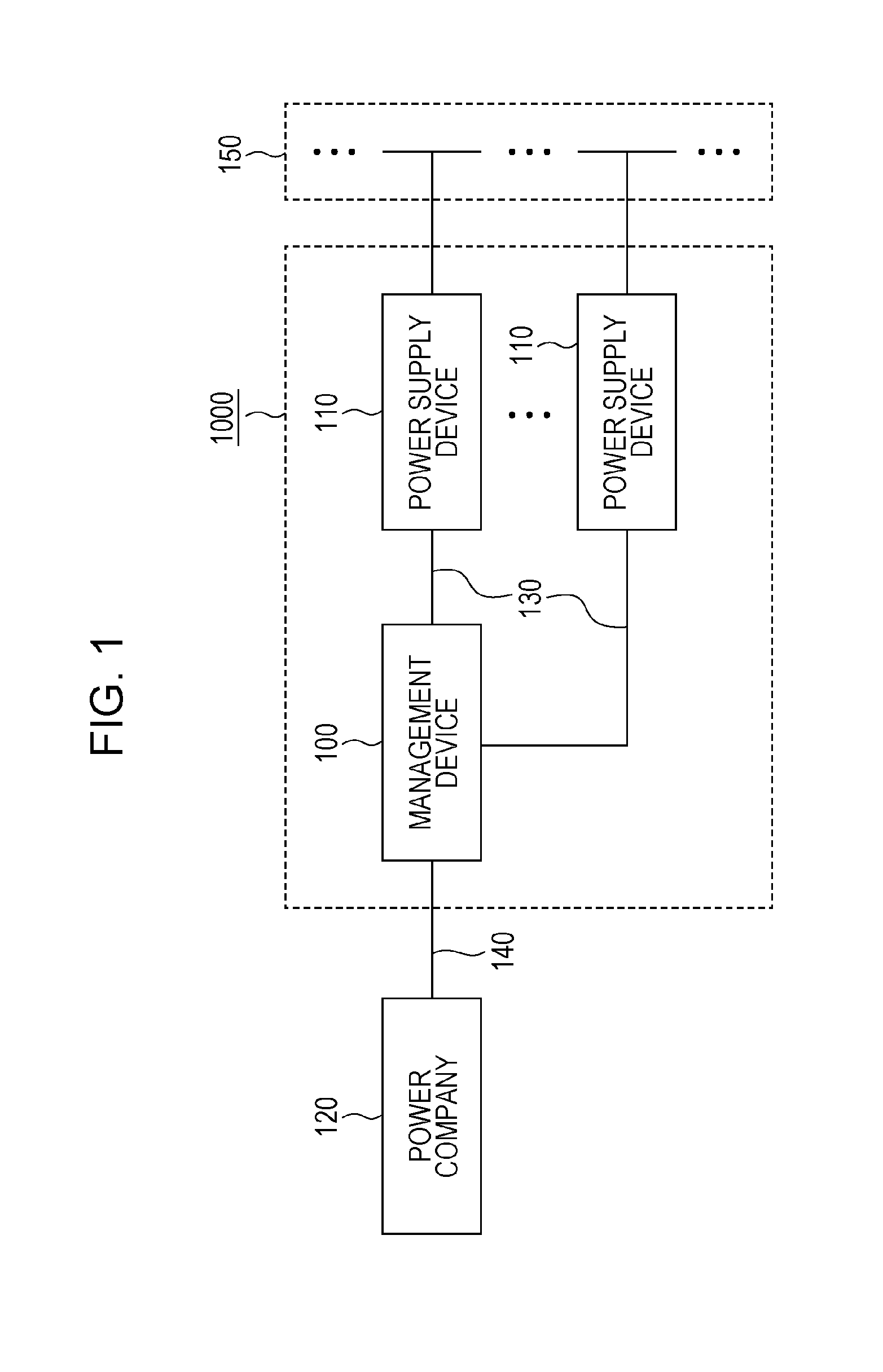
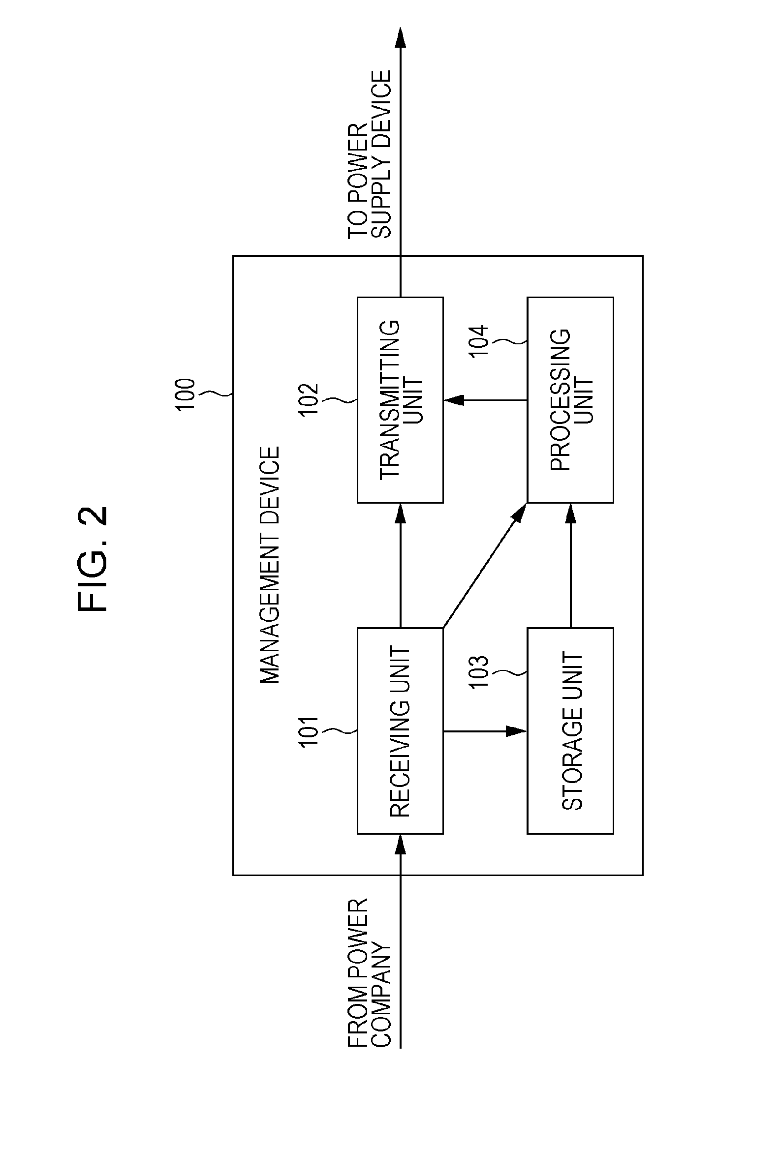
[0024]In the control system described in Patent Literature 1, since the power command value is generated by the management device, a power command value transmitted in advance may be recognized, and front-loading of the power command value may be realized. At this point, in the hypothetical case of a control system configured so that the management device executes control by receiving successive power command values from a power control center, there is a problem in that since the management device itself must wait for a power command value to arrive from the power control center, front-loaded control by the management device becomes difficult.

[0025]Accordingly, a power system stabilization method according to one aspect of the present disclosure is a power system stabilization method includes: receiving a power command value from a po...


PUM


Abstract

A power system stabilization method includes: receiving a power command value from a power control center that monitors a power system; transmitting the power command value to a power supply device; causing the power supply device to supply power to the power system according to the power command value; generating a prediction command value according to past power command values received from the power control center, the prediction command value being a prediction value of a power command value to be transmitted from the power control center next after the power command value; transmitting the prediction command value to a power supply device; causing the power supply device to supply power to the power system according to the power prediction command value; receiving the next power command value from the power control center; transmitting the next power command value to the power supply device.

Description

BACKGROUND[0001]1. Technical Field[0002]The present disclosure relates to a power system stabilization method that suitably maintains the power and frequency of a power system with an interconnected power supply device.[0003]2. Description of the Related Art[0004]In order to stabilize a power system, a power command value is transmitted to a power supply device connected to the power system from a management device that manages the power supply device, and the output power of the power supply device is controlled.[0005]The power command value may be transmitted to the power supply device from the management device using an Internet link, for example, but in some cases a variable communication delay occurs between the management device and the power supply device, and it may not be possible to execute control at the originally desired control timings.[0006]Accordingly, in the control system described in Japanese Unexamined Patent Application Publication No. 2009-219315 (Patent Litera...

Claims


Application Information

Patent Timeline
Patent Type & Authority Applications(United States)
IPC IPC(8): H02J3/12G05B15/02
CPCG05B15/02H02J3/12H02J3/32Y02B70/3225Y04S20/222H02J3/003H02J13/00028Y04S10/14Y04S10/50Y04S20/00Y02B90/20Y02E60/00H02J3/241H02J3/00
Inventor WATANABE, KENICHIMIYAZAKI, SEIYAKUDOH, TAKAHIROYAMAMOTO, YUTAKANAGAHARA, MASAAKINISHIDA, GOU
Owner PANASONIC CORP
Why Eureka
Try Eureka