

Owl, Double-bowl and slot-bump fluidic oscillator circuits, improved fluidic nozzle assemblies and methods for generating sprays with enhanced cold performance
- Summary
- Abstract
- Description
- Claims
- Application Information
AI Technical Summary
Benefits of technology
Problems solved by technology
Method used
Image

Examples
first embodiment
[0060]In operation, pressurized fluid flows into or enters through an inlet 110 or feed hole into the power nozzle 130 which terminates distally in a rectangular opening with a width dimension (“PW”) and a depth dimension (“PD”). There is a bell-shaped feed 130 leading to the power nozzle 150 which produces an accelerating fluid jet with a turbulent boundary layer that is desirable to form vortices inside interaction region 160. In this first embodiment, the fluidic circuit power nozzle 150 provides fluid to a jet-steering cavity section 140 which includes a first lateral fluid jet-steering cavity 142 opposite a second fluid jet-steering cavity 144, thus providing a pair of opposing, symmetrical fluid jet-steering cavities 142, 144. The size and shape of the cavities is identical, but mirror imaged and can be configured for varying fluid jet steering performance properties.
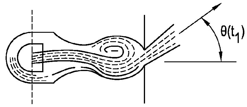
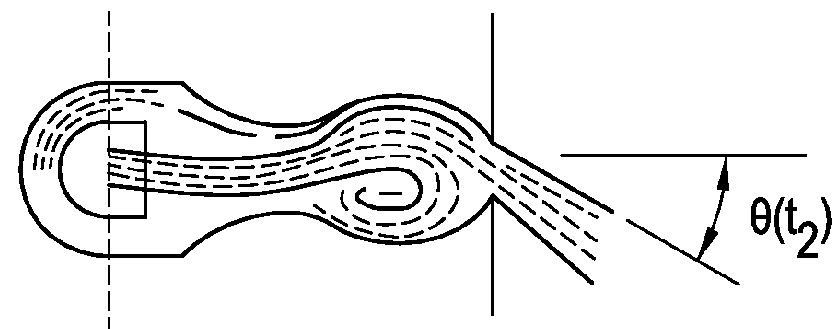
[0061]Seen in the plan view of FIG. 2A, circular cross section cavities 142, 144 will generate circulating flow...
second embodiment
[0083]In operation, pressurized fluid flows into or enters through an inlet 210 or feed hole into the bell shaped feed 230 terminating distally in a rectangular power nozzle opening 250 with a width dimension (“PW”) and a depth dimension (“PD”). The bell-shaped feed 230 leads to power nozzle 250 and which produces an accelerating fluid jet with a turbulent boundary layer that is desirable to form vortices inside interaction region 260. In this second embodiment, the fluidic circuit power nozzle 250 provides fluid to a jet-steering cavity section 240 which includes a first lateral fluid jet-steering cavity 242 opposite a second fluid jet-steering cavity 244, thus providing a pair of opposing, symmetrical fluid jet-steering cavities 242, 244. The size and substantially triangular shape of the cavities is identical, but mirror imaged and can be configured for varying fluid jet steering performance properties.
[0084]Seen in the plan views of FIGS. 3 and 4, triangular cross section caviti...
PUM
 Abstract
Description
Claims
Application Information