Bicycle tensioning device

a technology for tensioning devices and bicycles, which is applied in the direction of steering devices, cycle equipment, rod connections, etc., can solve the problems of front wheels not being able to be removed from the fork assembly, and achieve the effect of reducing the number of clamping holes

Active Publication Date: 2016-02-04
VOSS DARRELL W
View PDF4 Cites 13 Cited by
  • Summary
  • Abstract
  • Description
  • Claims
  • Application Information

AI Technical Summary

Benefits of technology

[0008]The present invention solves the above need in the art to not require loosing of a manually operated nut in order to remove a skewer rod and precise tightening of a manually operated nut in order to reinstall a skewer rod for frame designs utilizing through-holes instead of dropout slots to retain the wheel hub to the wheel mount—either the forks or the rear mount. This need is satisfied by use of a quick-release skewer assembly. The quick-release skewer assembly only requires a portion of a complete turn, such as quarter turn of a manually operated thumbnut to remove or reinstall the skewer rod, in one embodiment. In another embodiment, a quick-release lever only requires a portion of a turn, such as a quarter turn, to remove or reinstall the tensioning member. The present invention also allows for precise regulation of the clamping force applied to the left and right forks by the quick-release skewer assembly. The invention may be used with either front or rear dropout type mountings to provide an easier mount procedure and more consistent clamping force.

Problems solved by technology

The front wheel is not capable of being removed from the fork assembly without the skewer rod being removed from the through-holes in the lower portion of the left and right fork legs.

Method used


Image

  • Bicycle tensioning device
  • Bicycle tensioning device
  • Bicycle tensioning device

Examples


Embodiment Construction

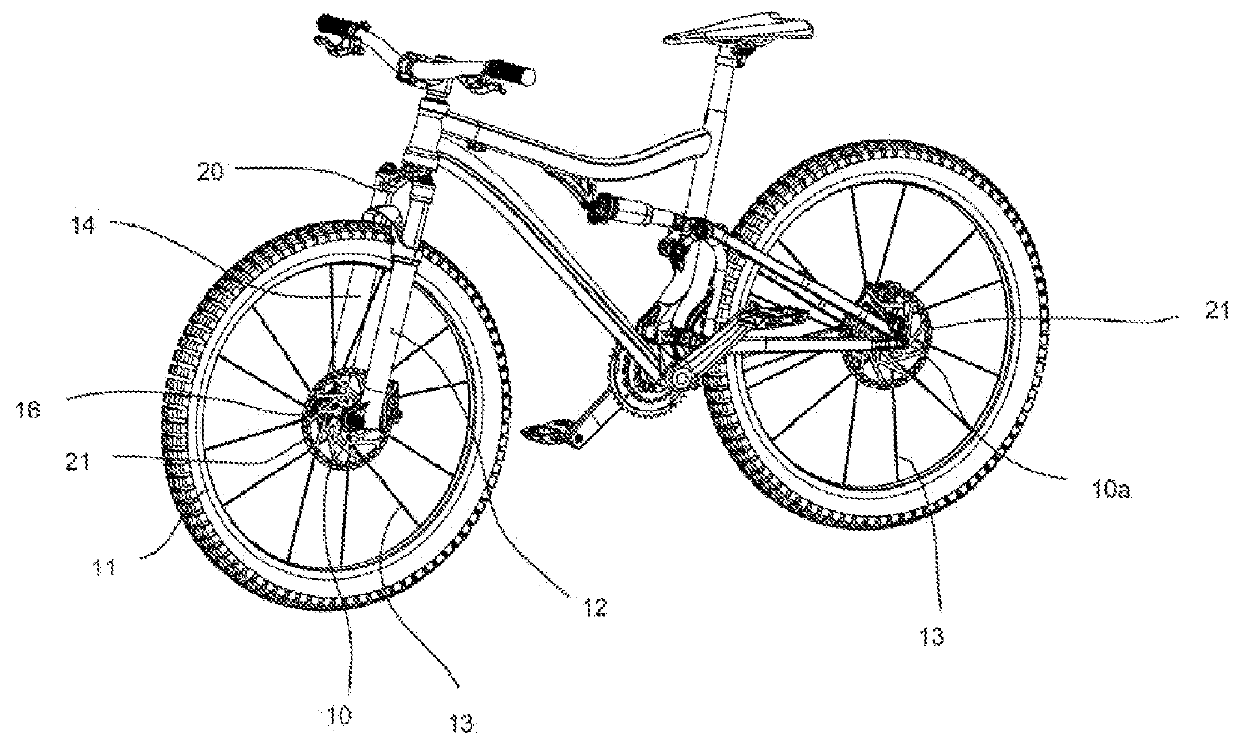
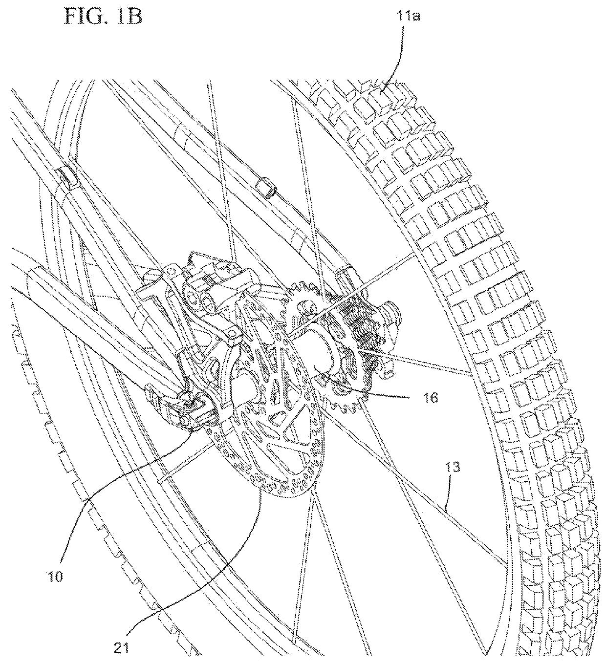
[0061]FIGS. 1A and B illustrate a bicycle having disc brakes, dropouts, and QR levers front and rear. The bicycle includes a quick-release skewer (i.e., tension rod assemblies) assemblies 10, 10a, a front wheel 11, rear wheel 11a, a hub assemblies 16 (partially hidden behind the brake discs in FIG. 1A), and a fork assembly 20. The front portion of the bicycle further includes a bicycle left fork leg 12, a bicycle right fork leg 14, bicycle spokes 13, and brake discs 21.

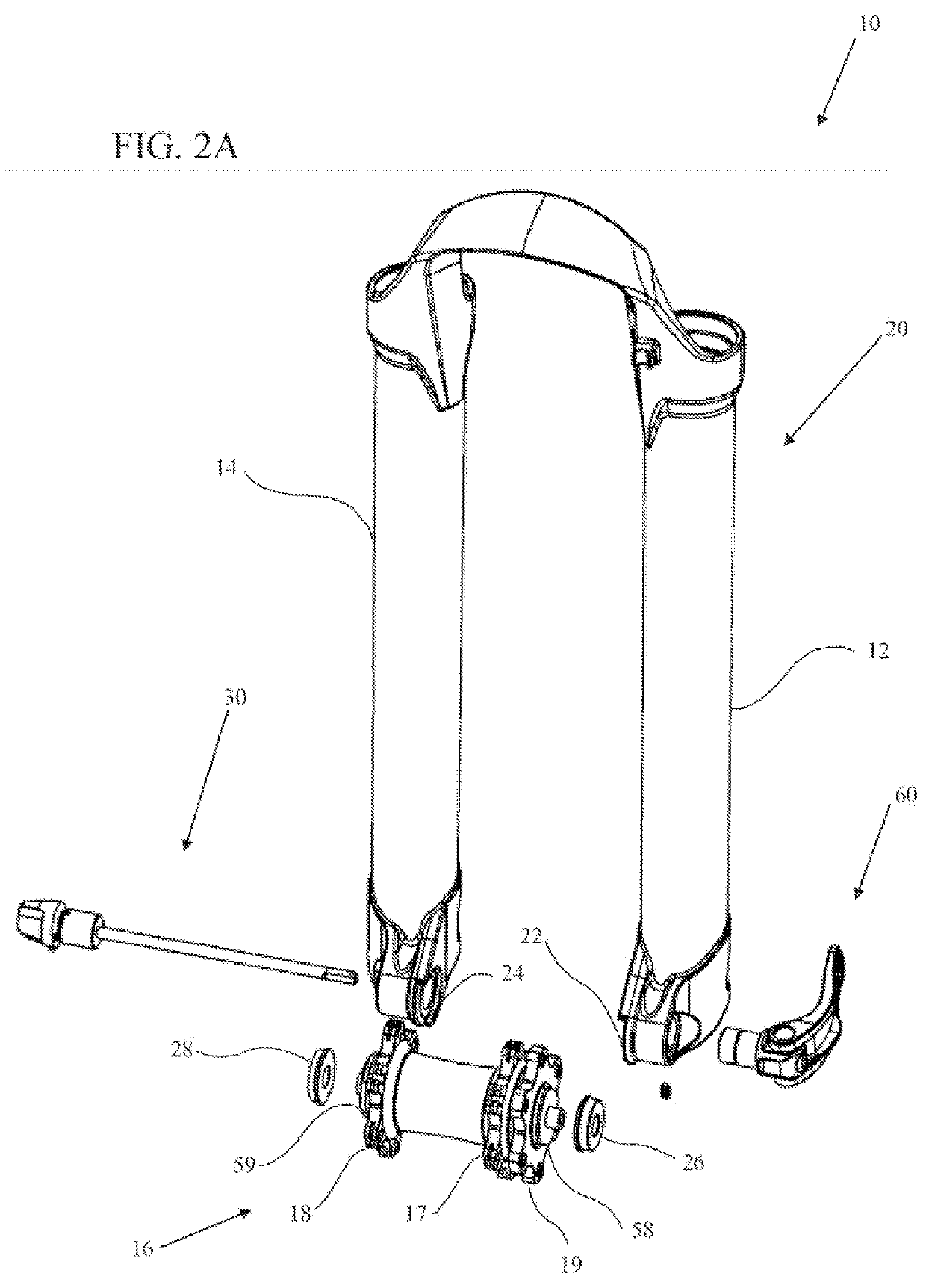
[0062]FIG. 2A illustrates an isometric view of a quick-release skewer assembly 10 and a fork assembly 20 looking toward a rear direction according to an embodiment. The quick-release skewer assembly of FIGS. 2 through 5 is primarily intended for hub assemblies 16 with a 9 mm axle, but the embodiments of FIGS. 2-5 are not limited to this size axle. As illustrated in FIG. 2, the quick-release skewer assembly 10 is mounted to a bicycle left fork leg 12 and a bicycle right fork leg 14. Located between the left bicycle for...


PUM


Abstract

A tensioning device for bicycle front and rear wheel assemblies. A skewer assembly with a thumbnut is securable to the wheel assembly with a quick-release assembly. Portions of the skewer assembly are removable from the quick-release assembly by turning the thumbnut a partial turn, such as a quarter of a turn. Removal of the skewer assembly allows the front wheel to be removed. In another embodiment, the skewer assembly is able to be removed by turning the quick-release assembly by a partial turn, such as a quarter of a turn.

Description

FIELD OF THE INVENTION[0001]The field of the invention relates generally to tension clamping members for a bicycle. The invention relates more particularly to a quick-release skewer assembly for securing a bicycle wheel.BACKGROUND OF THE INVENTION[0002]Bicycle quick-release mechanisms are utilized to allow a bicycle wheel to be quickly disconnected from the bicycle frame for repair, maintenance, securement to a bike rack, or shipping when the bicycle is not in use. Bicycle wheel quick-release (“QR”) mechanisms are available for both the front and rear wheels. Conventional quick-release mechanisms utilize a quick-release lever assembly located on one side of one of the bicycle dropouts—front and / or back. The term “dropout” herein refers to the wheel mount at the fork or rear of the bicycle, whether an open slot or a capturing hole for the axle to be secured within.[0003]The quick-release lever assembly attaches to one end of a skewer shaft. The other end of the skewer shaft is attach...

Claims


Application Information

Patent Timeline
Patent Type & Authority Applications(United States)
IPC IPC(8): B62K25/02
CPCB62K25/02B62K21/02B62K2025/025B60B27/026
Inventor VOSS, DARRELL, W.
Owner VOSS DARRELL W
Why Eureka
Try Eureka