Independent shutter system for rack-in breakers

a shutter system and rack-in technology, applied in the field of electrical systems, can solve the problems of restricting the amount of space available and not allowing the installation of additional switchgear components

Active Publication Date: 2016-02-04
SCHNEIDER ELECTRIC USA INC
View PDF5 Cites 22 Cited by
  • Summary
  • Abstract
  • Description
  • Claims
  • Application Information

AI Technical Summary

Benefits of technology

[0006]In another alternative implementation of the present invention, a switchgear interlock system includes a circuit breaker with a cluster shield extending rearwardly and a back-mold with attached bus connectors. At least two independently movable shutters are mounted on the back-mold parallel to each other, each of the shutters including a pedestal fixedly mounted to the back-mold. Each shutter further includes a mount movably attached to the pedestal, and a curtain attached to the mount. The curtain has two slidable hands movable between an open position and a closed position. The hands are movable away from each other from the closed position to the open position in response to the mount being forced towards the back-mold along the pedestal. The hands are movable towards each other from the open position to the closed position in response to a return force applied by a spring. The system further includes a crossbar movable between a locked state and an unlocked state in response to a single user input. The locked state prevents movement of the hands in the closed position for each of the shutters.

Problems solved by technology

As such, the present shutter system restricts the amount of space available between the phases and does not allow installation of additional switchgear components.

Method used


Image

  • Independent shutter system for rack-in breakers
  • Independent shutter system for rack-in breakers
  • Independent shutter system for rack-in breakers

Examples


Embodiment Construction

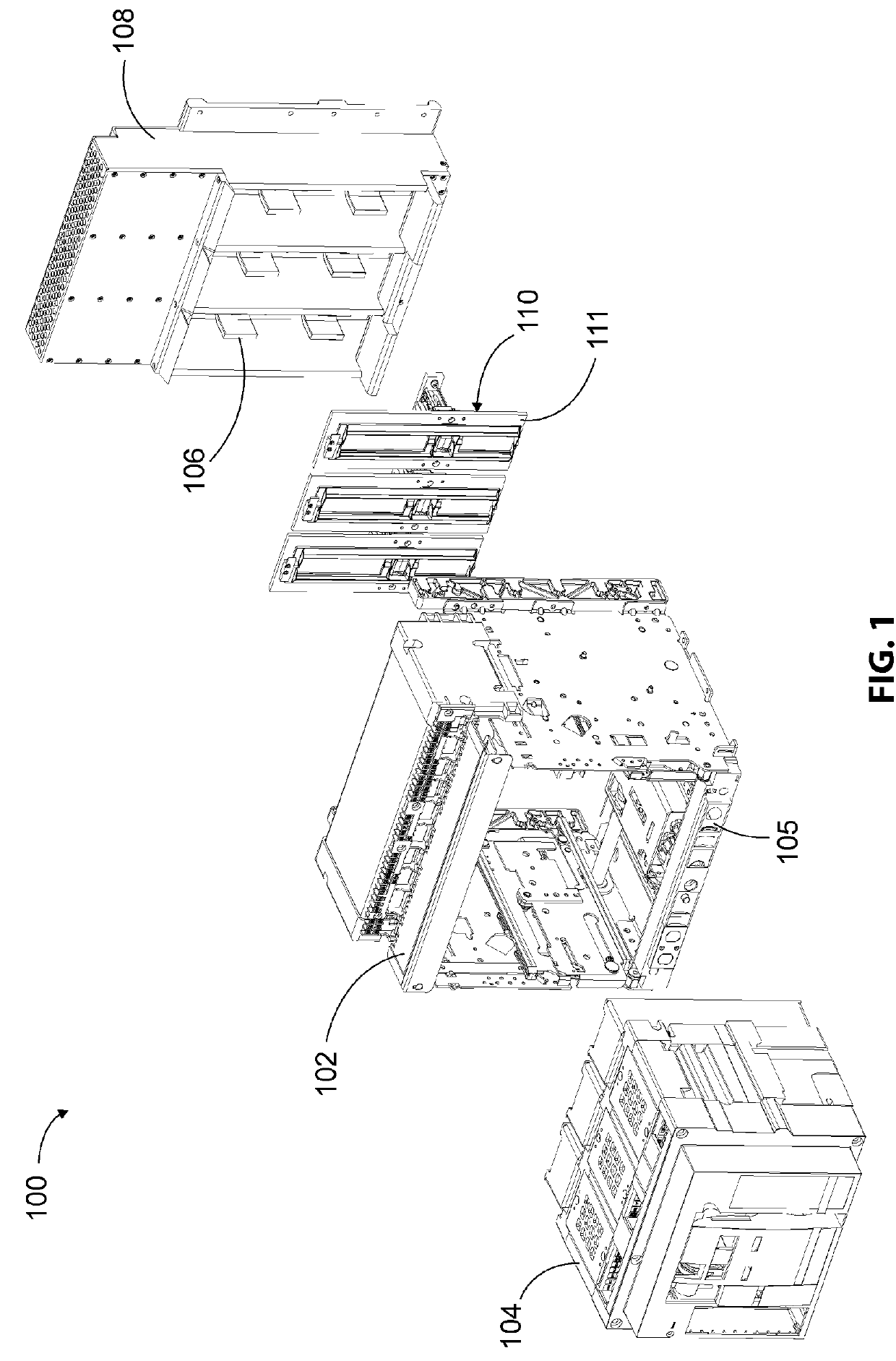
[0038]Referring to FIG. 1, a switchgear system 100 is typically installed in a switchgear cabinet (not shown) along with other electrical equipment for distributing, controlling, and / or protecting electrical equipment. The switchgear system 100 includes a chassis 102 for receiving a draw-out circuit breaker 104, which is movable in and out of contact with an electrical supply. The electrical supply is received via one or more bus bars (not shown) having bus connectors, collectively 106, that extend towards the circuit breaker 104 from a back-mold 108. To protect inadvertent contact with the bus connectors 106 when the circuit breaker 104 is in a test position or in a disconnected position (i.e., when the circuit breaker 104 is disconnected from the electrical supply), an independent shutter assembly 110 is attached to the back-mold 108. The chassis 102 includes a front surface 105 that has a recessed area in which an indicator 310 (shown in FIG. 23) is positioned.

[0039]The shutter a...


PUM


Abstract

A switchgear interlock system includes a circuit breaker with clusters of connector fingers separated from each other by respective cluster shields. In a connected position, the connector fingers engage respective bus connectors of bus bars for electrical contact. When the circuit breaker is disconnected from the bus bars, independently movable shutters cover access to the bus connectors to prevent inadvertent contact with the bus connectors. Each shutter includes a pedestal with an attached movable mount and movable curtain. As the circuit breaker is moved into the connected position, the mount slides along the pedestal towards the bus connector causing the curtain to open and allow the connector fingers to engage the bus connectors. As the circuit breaker is being disconnected, a return spring causes the mount to slide along the pedestal away from the bus connectors causing the curtain to close and prevent access to the bus connectors.

Description

FIELD OF THE INVENTION[0001]This invention is directed generally to electrical systems, and, more particularly, to a switchgear system with independently movable shutters for protecting bus connectors.BACKGROUND OF THE INVENTION[0002]Circuit breakers used in switchgear systems are often built with a draw-out configuration, which allows breaker insertion or removal in a cradle assembly without disturbing power circuit connections. The draw-out breakers have a connected position in which connector fingers of the breakers are connected to respective bus connectors of bus bars, and a test position in which the connector fingers are disconnected from the bus connectors. To cover access to, and prevent inadvertent contact with, the bus connectors when the breaker is in the test position, a common shutter system has been presently utilized across a back plane of the cradle assembly. The shutter system includes sliding panels that protect all breaker phases at the same time. The shutter sys...

Claims


Application Information

Patent Timeline
Patent Type & Authority Applications(United States)
IPC IPC(8): H02B11/24H02B11/133
CPCH02B11/133H02B11/24
Inventor SCHROEDER, DAVID
Owner SCHNEIDER ELECTRIC USA INC
Why Eureka
Try Eureka