Gateway device, network system including gateway device, air-conditioning outdoor unit, and air-conditioning network system

Inactive Publication Date: 2016-02-04
MITSUBISHI ELECTRIC CORP
View PDF0 Cites 5 Cited by
  • Summary
  • Abstract
  • Description
  • Claims
  • Application Information

AI Technical Summary

Benefits of technology

[0011]A gateway device according to the present invention has the configuration described above, so that it can realize broadcast or multicast communication that matches the areas of the address archite

Problems solved by technology

On the other hand, due to an improvement in function of the facility instrument, the communicatio

Method used


Image

  • Gateway device, network system including gateway device, air-conditioning outdoor unit, and air-conditioning network system
  • Gateway device, network system including gateway device, air-conditioning outdoor unit, and air-conditioning network system
  • Gateway device, network system including gateway device, air-conditioning outdoor unit, and air-conditioning network system

Examples


embodiment 1

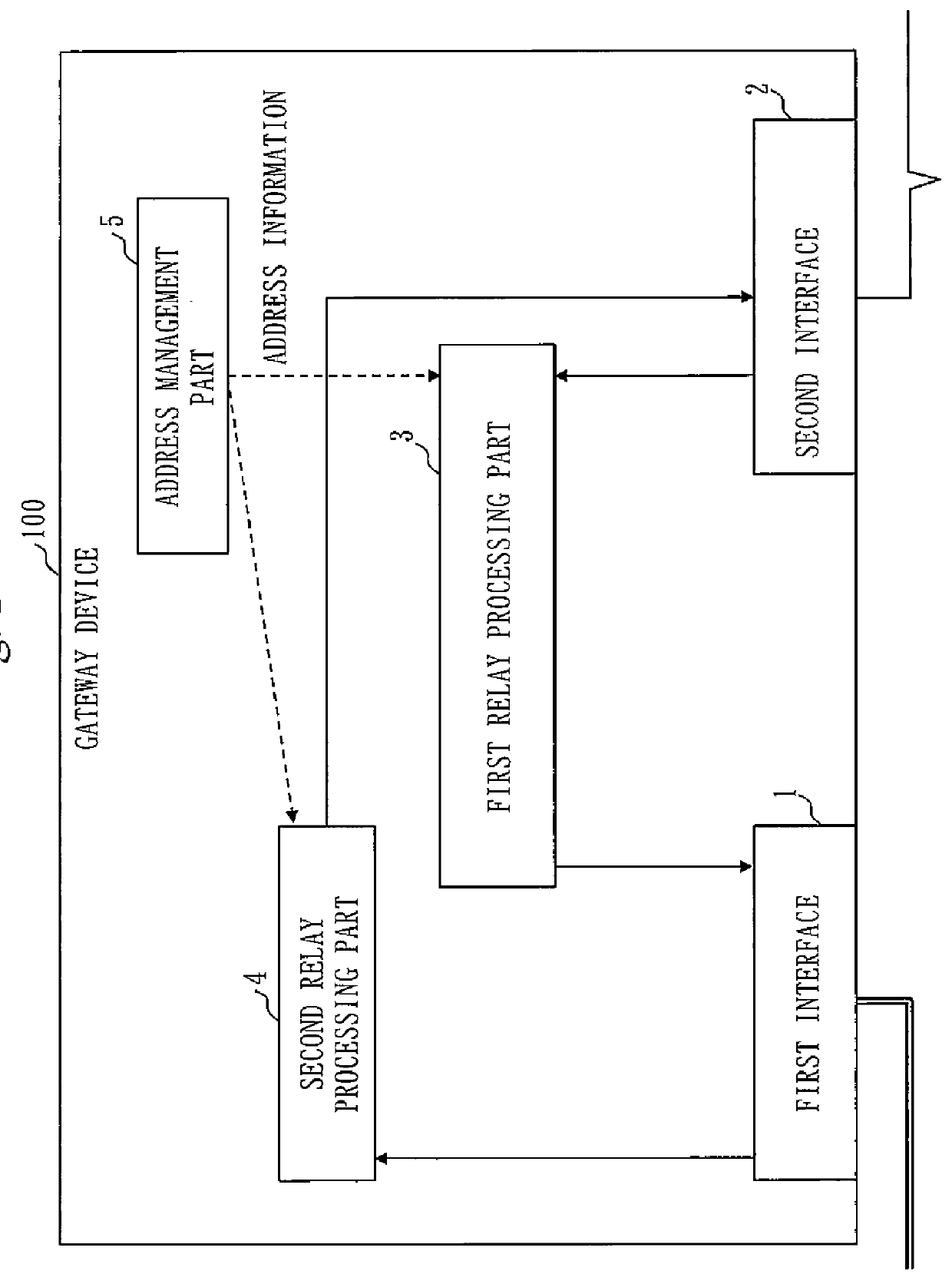
[0021]FIG. 1 is a diagram illustrating a gateway device in a facility network according to Embodiment 1.

[0022]The configuration will be described.

[0023]A gateway device 100 is constituted by a first interface 1, a second interface 2, a first relay processing part 3, a second relay processing part 4, and an address management part 5.

[0024]The first interface 1 is an interface to be connected to a non-band-sharing broader-band network between two types networks to be connected to the gateway device 100. For an example, an interface employing Ethernet (registered trademark) is used.

[0025]The second interface 2 is an interface to be connected to a band-sharing narrower-band network between the two types of networks to be connected to the gateway device 100. The present invention, while not limiting a practical network type, is particularly of greater utility in a case of half-duplex communication or in a case where a low-speed network is connected.

[0026]The first relay processing part 3...

embodiment 2

[0057]Embodiment 2 will describe a configuration which is provided with the entire configuration and operation of Embodiment 1 and which additionally includes an address storage processing part 6.

[0058]FIG. 4 is a diagram illustrating a gateway device 100 in a facility network according to Embodiment 2.

[0059]An address storage processing part 6 of the gateway device 100 has the following functions. The address storage processing part 6 monitors data received from a second interface 2 and acquires a sender address included in the data, thereby holding address information on a communication device connected to the second interface 2. The address storage processing part 6 also provides the address information it saves in response to a request from a first relay processing part 3.

[0060]The first relay processing part 3 processes multicast or broadcast data received by the second interface 2, in the same manner as in Embodiment 1, and processes unicast data in the following manner.

[0061]...

embodiment 3

[0073]Embodiment 3 will describe a configuration which is provided with the entire configuration of Embodiment 2 and which additionally includes a gateway address management part 7.

[0074]FIG. 6 is a configuration diagram of a gateway device 100 according to Embodiment 3.

[0075]The gateway address management part 7 has the following functions. The gateway address management part 7 monitors data received from a first interface 1 and extracts, from the received data, address information (the address of the broadband network) of the sender gateway and address information (the address of the narrow-band network) of the sender communication device which has been included in pre-encapsulation data within the received data. The gateway address management part 7 pairs the two types of address information and stores the pair. The gateway address management part 7 also provides information on the address pair which is to be provided in response to a request from a first relay processing part 3....


PUM


Abstract

A gateway device includes an address manager that manages address information enabling transmission via a second interface of an own gateway device and another gateway device, a first relay that, if the data received by the second interface is multicast data, adds to the multicast data received, address information and a header conforming to a protocol of a non-band-sharing network, and outputs the multicast data to a first interface, and a second relay that, if the data received by the first interface includes address information, extracts only multicast data from data conforming to the protocol of the non-band-sharing network, and transmits the multicast data to the second interface. Even when collision domain for N (N is 2 or more) of facility networks having different address architectures is to be divided using (N+1) or more of gateways, multicast communication that match the area of the address architecture can be realized.

Description

TECHNICAL FIELD[0001]The present invention relates to a facility network that uses a gateway device.BACKGROUND ART[0002]In the field of so-called facility network, a network that uses band-sharing communication media has conventionally been employed. The band-sharing communication media generally have a very narrow band but are in use continuously even today in various types of facility instruments for different reasons regarding, for example, cost performance, operation performance, and connection with existing instruments.[0003]On the other hand, due to an improvement in function of the facility instrument, the communication quantity required by devices increases, posing a problem of the insufficient communication band.[0004]In a conventional facility network system, when the communication collision domain is shared by all facility instruments, the collision domain is divided into a plurality of sub-domains, so that the communication band is used efficiently (for example, Patent L...

Claims


Application Information

Patent Timeline
IPC IPC(8): H04L12/18F24F11/00H04L45/16
CPCH04L12/18F24F2011/0071F24F11/006H04L45/16H04L12/1886F24F11/30F24F11/62F24F11/58F24F11/63H04L12/1836H04L12/2836H04L12/4633H04L12/66H04L67/12H04L41/12H04L69/18H04L61/5069
Inventor HAMADA, KAZUKIKITAICHI, RYUICHI
Owner MITSUBISHI ELECTRIC CORP
Why Eureka
Try Eureka