Modular wall system for vertical gardens

Inactive Publication Date: 2016-02-11
MODIWALL PTY
View PDF14 Cites 15 Cited by
  • Summary
  • Abstract
  • Description
  • Claims
  • Application Information

AI Technical Summary

Benefits of technology

The patent describes a system for guiding liquids along a panel and allows for the panels to be connected together to create different structures. The panels have channels or grooves that evenly distribute the liquid along the panel. The panels can also be connected together with pivotal connections, creating a flexible and adjustable structure. The technical effect of this patent is that it allows for the creation of various structures using liquid guidance and pivotal connections.

Problems solved by technology

However, this arrangement suffers from a number of disadvantages, such as (i) it can only house a relatively small amount of growing medium, which limits plant growth and life over time; (ii) it requires liquid nutrients to extend plant growth and life due to unnatural growing conditions; (iii) unpleasant odors being created by the use of significant amounts of liquid nutrients; (iv) requiring relatively high maintenance to maintain irrigation and encourage healthy plant growth; (v) requiring expensive matt pocket and bag kits; (vi) having a relative high watering demand to encourage plant growth and to keep plants hydrated; and (vii) being relatively difficult to manufacture, install and maintain.
Additional problems associated with vertical gardens include uneven water distribution through the wall, as water is required to trickle downwardly from a top of the wall through the growing medium for the width and height of the wall that is covered by plants.
If the water is not evenly distributed some plants may be over-watered, while other plants in the wall may be under-watered.
Moreover, existing systems for vertical gardens seldom provide for interchangeability in its design, at least not without significant difficulty—once the plants are in place, they can generally not be moved easily to manipulate the design of such a living wall.

Method used


Image

  • Modular wall system for vertical gardens
  • Modular wall system for vertical gardens
  • Modular wall system for vertical gardens

Examples


Embodiment Construction

[0029]Without limiting the scope thereof, the invention will now further be described by way of example only and with reference to the accompanying drawings in which—

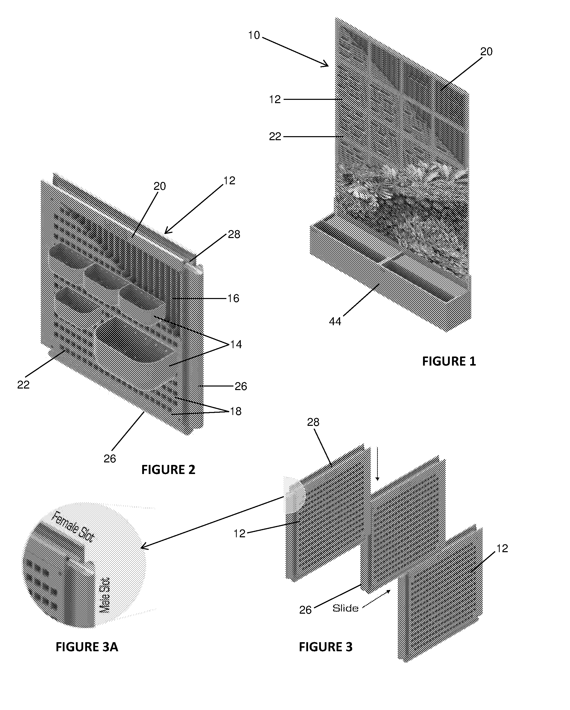
[0030]FIG. 1 is a partially sectioned perspective view of an assembled modular wall structure according to the invention;

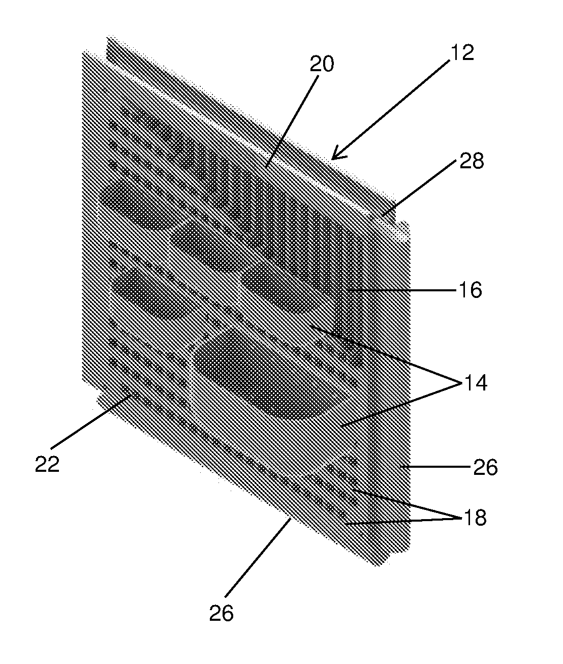
[0031]FIG. 2 is partially sectioned perspective view of a supporting wall of the modular wall structure, illustrating the manner in which a variety of plant containers are releasably connectable to the supporting wall;

[0032]FIG. 3 is a perspective view of three supporting walls, illustrating the manner in which neighboring supporting walls can engage each other to form different structures, depending on on-site design requirements;

[0033]FIG. 3 is an exploded view of a corner of a wall unit of FIG. 3, illustrating the male and female formations;

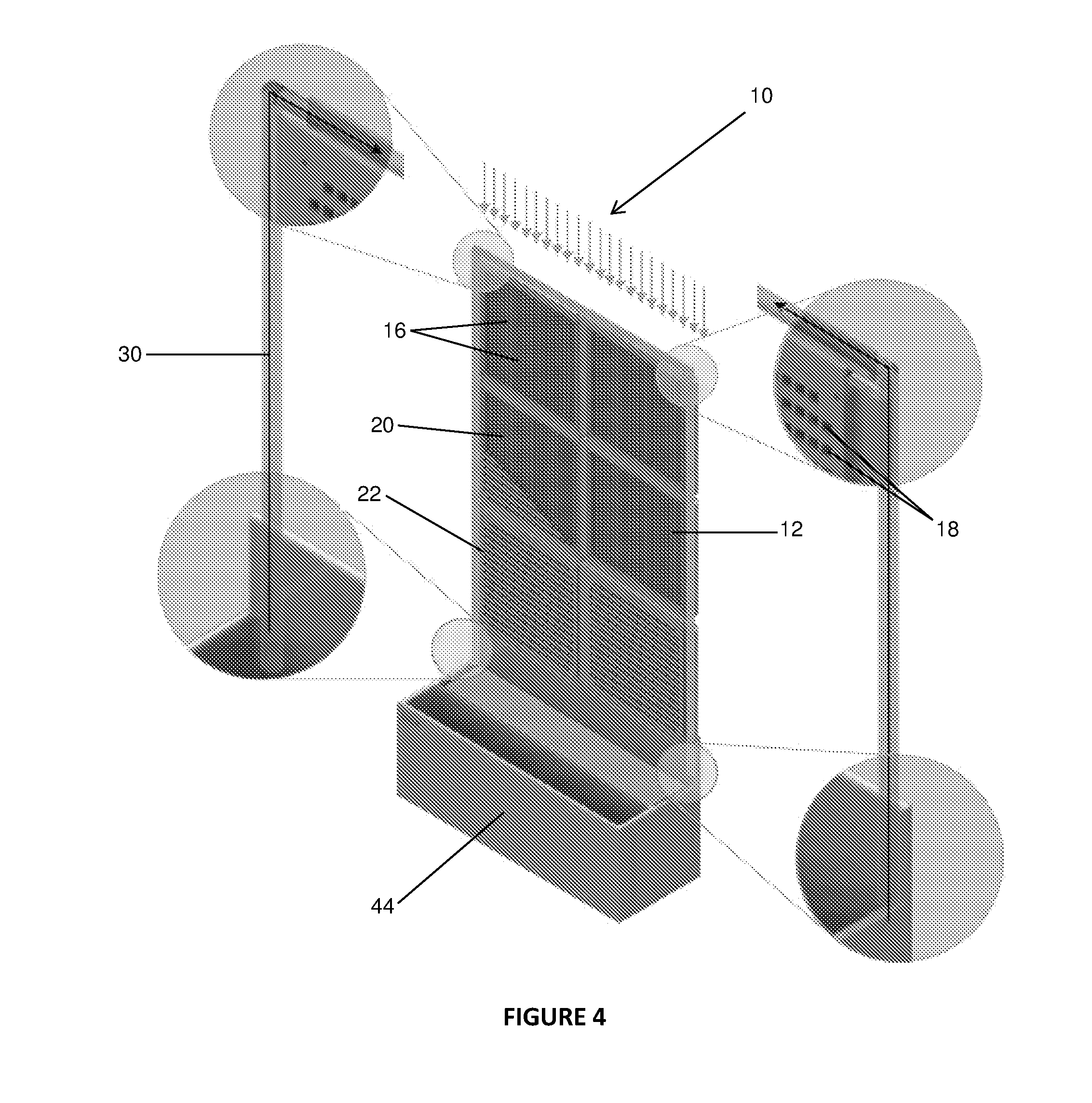
[0034]FIG. 4 is an exploded, partially sectioned, perspective view of a modular wall system according to the invention;

[0035]FIG. 5 is a perspective view of a f...


PUM


Abstract

The invention provides a modular wall system [10] which is adapted for supporting a vertical garden. The modular wall system [10] comprises a supporting wall [12] comprising first liquid guiding means [16] for guiding water, liquid nutrient feedstock and the like in the wall [12], and first engaging means [18] for engaging a plant container [14] in various different positions on the supporting wall [12]. The modular wall system [10] also comprises at least one plant container [14] for housing plant material, wherein the plant container [14] comprises second engaging means [32] for releasably engaging the supporting wall [12], and second liquid guiding means [34, 36] extending from the plant container [14] into the first liquid guiding means [16] and dimensioned for guiding liquid from the first liquid guiding means [16] in the supporting wall [12] into the plant container [14].

Description

INTRODUCTION TO THE INVENTION[0001]This invention relates to a modular wall system adapted for supporting a vertical garden, both indoors and outdoors.BACKGROUND TO THE INVENTION[0002]A “living wall” or “vertical garden”, which is also referred to as a green wall, bio-wall or vertical vegetated complex wall, is a wall, either free-standing or as part of a building, which is partially or completely covered with vegetation and, in some cases, soil or an inorganic growing medium. Vertical gardens can be designed into water features, landscapes, buildings and intimate urban yards and is becoming increasingly popular in the design of modern-day structures where space is often limited, but where the benefit of “green living” is highly sought after by architects, business owners and homeowners alike.[0003]Those who are engaged in the landscaping industry will appreciate that vertical garden systems typically incorporate a so-called “matt pocket and bag” method. However, this arrangement su...

Claims


Application Information

Patent Timeline
IPC IPC(8): A01G27/00A01G9/02
CPCA01G27/005A01G9/025Y02P60/20A01G9/022A01G27/00A01G27/04
Inventor BAKER, CHARLSMIT, PAUL RUDOLPHDU TOIT, WILLEM GERT
Owner MODIWALL PTY
Why Eureka
Try Eureka