Continuously variable transmission

Inactive Publication Date: 2016-02-18
CATERPILLAR INC
View PDF0 Cites 4 Cited by
  • Summary
  • Abstract
  • Description
  • Claims
  • Application Information

AI Technical Summary

Problems solved by technology

Such and other known CVT drive arrangements usually have low power transmission efficiency, for example, less than about 90%, but are still widely used because they c

Method used


Image

  • Continuously variable transmission
  • Continuously variable transmission
  • Continuously variable transmission

Examples


Example

[0015]The present disclosure relates to powertrains and, specifically, to a continuously variable transmission (CVT) for use in any type of application. For example, the CVT embodiments disclosed herein are suitable for use in vehicle powertrains such as passenger automobiles, trucks, machines and other land-based vehicles, as well as for other applications such as in marine propulsion systems, stationary machines, and the like. The particular applications to a machine described herein are equally applicable to other types of machines having different types of transmissions. Therefore, one exemplary application to a wheel loader is shown herein, but it should not be construed as limiting the scope of the disclosure or the claims.

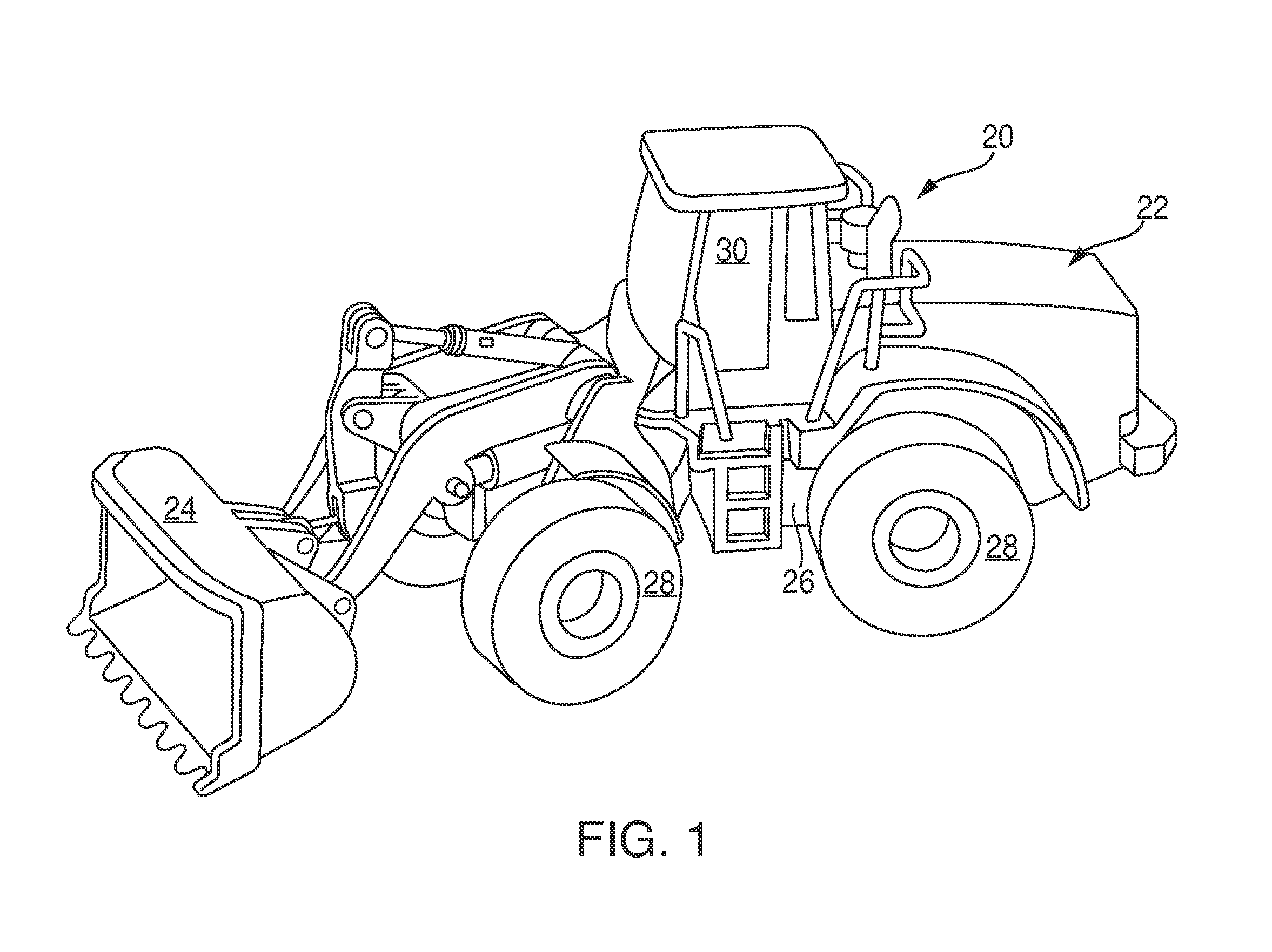
[0016]Referring now to the drawings, in which like reference numerals represent like parts throughout the several views, FIG. 1 shows a loader 20 in accordance with an embodiment. The loader 20 includes a vehicle portion 22 connected to a bucket or implement...


PUM


Abstract

A continuously variable transmission (CVT) includes an input arrangement associated with an input shaft and an output arrangement associated with an output shaft. An input sprocket and an output sprocket are connected via a chain. An input cone member is connected to the input shaft, disposed within a central opening of the input sprocket, and frictionally engages an inner periphery of the input sprocket such that rotation of the input cone causes the input sprocket to rotate. An output cone member is connected to the output shaft, disposed within a central opening of the output sprocket, and frictionally engages an inner periphery of the output sprocket such that rotation of the output sprocket causes rotation of the output cone member.

Description

TECHNICAL FIELD[0001]This patent disclosure relates generally to machines and, more particularly, to a continuously variable transmission for use in a vehicle powertrain.BACKGROUND[0002]Continuously variable transmission (CVT) arrangements in powertrains for use in vehicles such as cars and other machines are known. A typical CVT is a device that can assume almost an infinite number of effective gear ratios between maximum and minimum values between an input shaft and an output shaft of the powertrain in which the CVT is installed. In certain applications, this capability of the CVT allows the input shaft, for example, an engine, to operate at a constant speed while traction elements of the powertrain can rotate at variable speeds.[0003]Various known CVT types include variable diameter-pulley (VDP) or Reeves-type, toroidal or roller-based, magnetic, infinitely variable, ratcheting, incremental, radial roller, cone roller, and other drive arrangement types. In certain drive arrangeme...

Claims


Application Information

Patent Timeline
IPC IPC(8): F16H9/24F16H55/30F16H55/36
CPCF16H9/24F16H55/30F16H55/36F16H7/06F16H15/18F16H37/12F16H55/56
Inventor ELLICOTT, GABRIEL, J.
Owner CATERPILLAR INC
Why Eureka
Try Eureka