System and method for identifying suboptimal microphone performance

a microphone performance and suboptimal technology, applied in the field of signal processing systems, can solve the problems of microphone fabrication process, non-uniform characteristics of microphones used in signal processing systems, and inability to meet the needs of instrumentation,

Active Publication Date: 2016-02-18
CERENCE OPERATING CO
View PDF5 Cites 128 Cited by
  • Summary
  • Abstract
  • Description
  • Claims
  • Application Information

AI Technical Summary

Benefits of technology

[0004]One or more of the following features may be included. In some embodiments, detecting the obstructed microphone may include identifying at least one low-pass characteristic associated with the obstructed microphone. The method may further include deactivating the obstructed microphone. In some embodiments, in response to detecting the obstructed microphone, the method may include deactivating a beamforming setting associated with the computing device. The method may further include identifying a microphone channel based upon, at least in part, a signal-to-noise ratio analysis. The method may also include generating, at the computing device, a feedback signal configured to indicate the presence of the obstructed microphone. In some embodiments, the third speech signal magnitude is at least one of the first speech signal magnitude, second speech signal magnitude, a median of a plurality of speech magnitudes, and a reference speech signal magnitude.
[0005]In another implementation, a system is provided. The system may include a computing device including one or more processors configured to determine a parameter of a first microphone and a second microphone, wherein the first microphone and the second microphone are associated with the computing device. The one or more processors may be further configured to generate a reference parameter based upon, at least in part, at least one of the parameter of the first microphone and the signal parameter of the second microphone. The one or more processors may be further configured to adjust a tolerance of at least one of the first microphone and the second microphone, based upon, at least in part, the reference parameter. The one or more processors may be further configured to receive, at the first microphone, a first speech signal corresponding to an utterance of a speaker, the first speech signal having a first speech signal magnitude. The one or more processors may be further configured to receive, at the second microphone, a second speech signal corresponding to the utterance of the speaker, the second speech signal having a second speech signal magnitude. The one or more processors may be further configured to compare at least one of the first speech signal magnitude and the second speech signal magnitude with a third speech signal magnitude. The one or more processors may be further configured to detect an obstructed microphone based upon, at least in part, the comparison.
[0006]One or more of the following features may be included. In some embodiments, detecting the obstructed microphone may include identifying at least one low-pass characteristic associated with the obstructed microphone. The one or more processors may be further configured to deactivate the obstructed microphone. In some embodiments, in response to detecting the obstructed microphone, the one or more processors may be further configured to deactivate a beamforming setting associated with the computing device. In some embodiments, the one or more processors may be further configured to identify a microphone channel based upon, at least in part, a signal-to-noise ratio analysis. In some embodiments, the one or more processors may be further configured to generate at the computing device, a feedback signal configured to indicate the presence of the obstructed microphone. In some embodiments, the third speech signal magnitude is at least one of the first speech signal magnitude, second speech signal magnitude, a median of a plurality of speech magnitudes, and a reference speech signal magnitude.
[0007]In another implementation, a computer program product is provided. The computer program product may include a non-transitory computer readable medium having stored thereon instructions, which when executed result in one or more operations. Operations may include determining a parameter of a first microphone and a second microphone, wherein the first microphone and the second microphone are associated with a computing device. Operations may further include generating a reference parameter based upon, at least in part, at least one of the parameter of the first microphone and the frequency response of the second microphone. Operations may also include adjusting a tolerance of at least one of the first microphone and the second microphone, based upon, at least in part, the reference parameter. Operations may further include receiving, at the first microphone, a first speech signal corresponding to an utterance of a speaker, the first speech signal having a first speech signal magnitude. Operations may additionally include receiving, at the second microphone, a second speech signal corresponding to the utterance of the speaker, the second speech signal having a second speech signal magnitude. Operations may also include comparing at least one of the first speech signal magnitude and the second speech signal magnitude with a third speech signal magnitude and detecting an obstructed microphone based upon, at least in part, the comparison.
[0008]One or more of the following features may be included. In some embodiments, detecting the obstructed microphone may include identifying at least one low-pass characteristic associated with the obstructed microphone. Operations may further include deactivating the obstructed microphone. In some embodiments, in response to detecting the obstructed microphone, operations may include deactivating a beamforming setting associated with the computing device. Operations may further include identifying a microphone channel based upon, at least in part, a signal-to-noise ratio analysis. Operations may also include generating, at the computing device, a feedback signal configured to indicate the presence of the obstructed microphone. In some embodiments, the third speech signal magnitude may be at least one of the first speech signal magnitude, second speech signal magnitude, a median of a plurality of speech magnitudes, and a reference speech signal magnitude.
[0009]The details of one or more implementations are set forth in the accompanying drawings and the description below. Other features and advantages will become apparent from the description, the drawings, and the claims.

Problems solved by technology

Microphones used in signal processing systems often have non-uniform characteristics.
Non-uniform microphone characteristics may result from variations in the microphone fabrication process, from changes arising in the microphones from age, use, temperature, humidity, altitude, or from other factors.
Non-uniform microphone characteristics may result in non-uniform frequency response between microphones, reduced signal strength and sampling accuracy, inconsistent sampling of sound signals, and generally reduced system performance.
Occasionally, a non-uniform microphone characteristic may occur as a result of an obstructed microphone (e.g. user blocking the microphone with his / her hand, etc.).

Method used


Image

  • System and method for identifying suboptimal microphone performance
  • System and method for identifying suboptimal microphone performance
  • System and method for identifying suboptimal microphone performance

Examples


Embodiment Construction

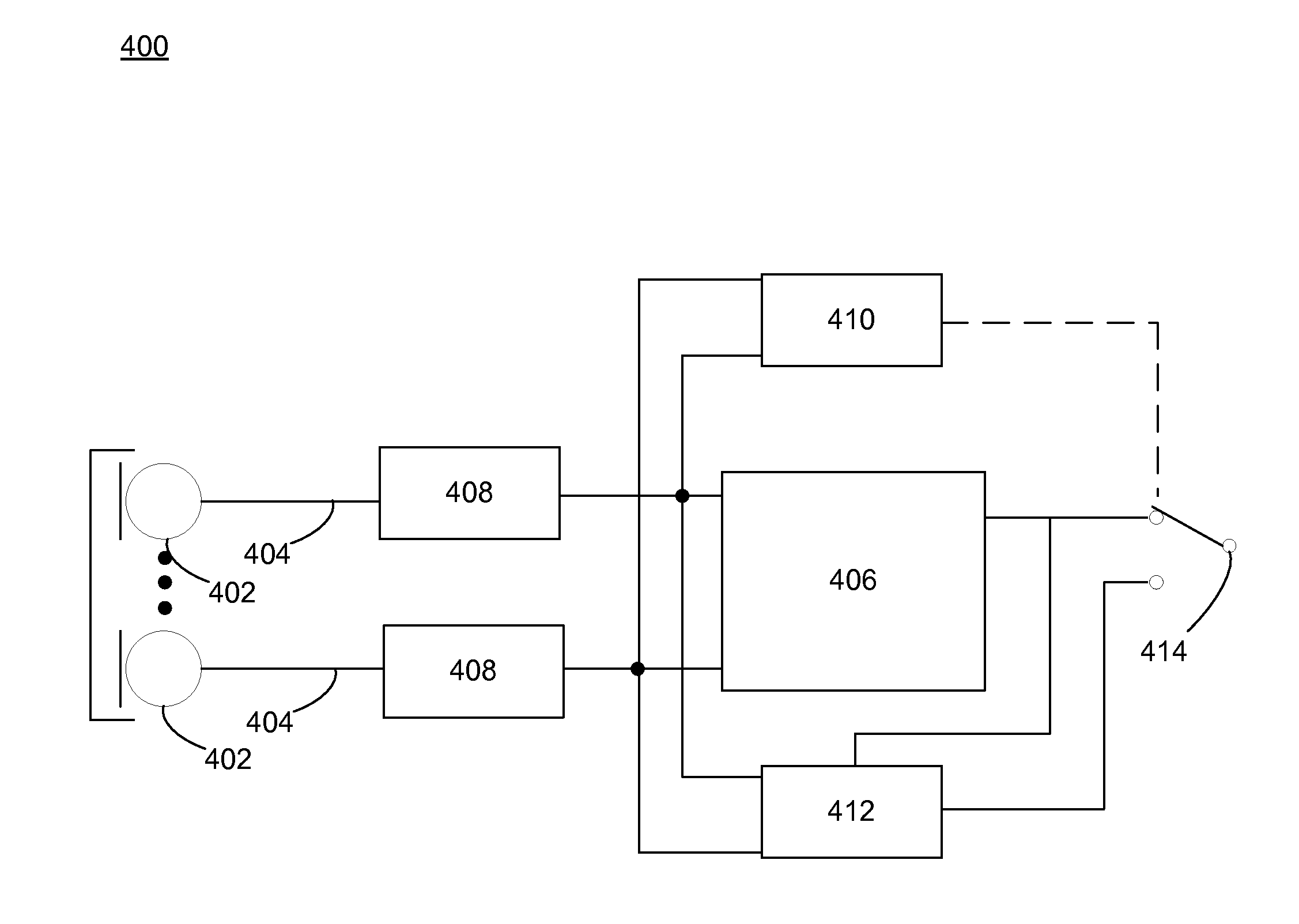
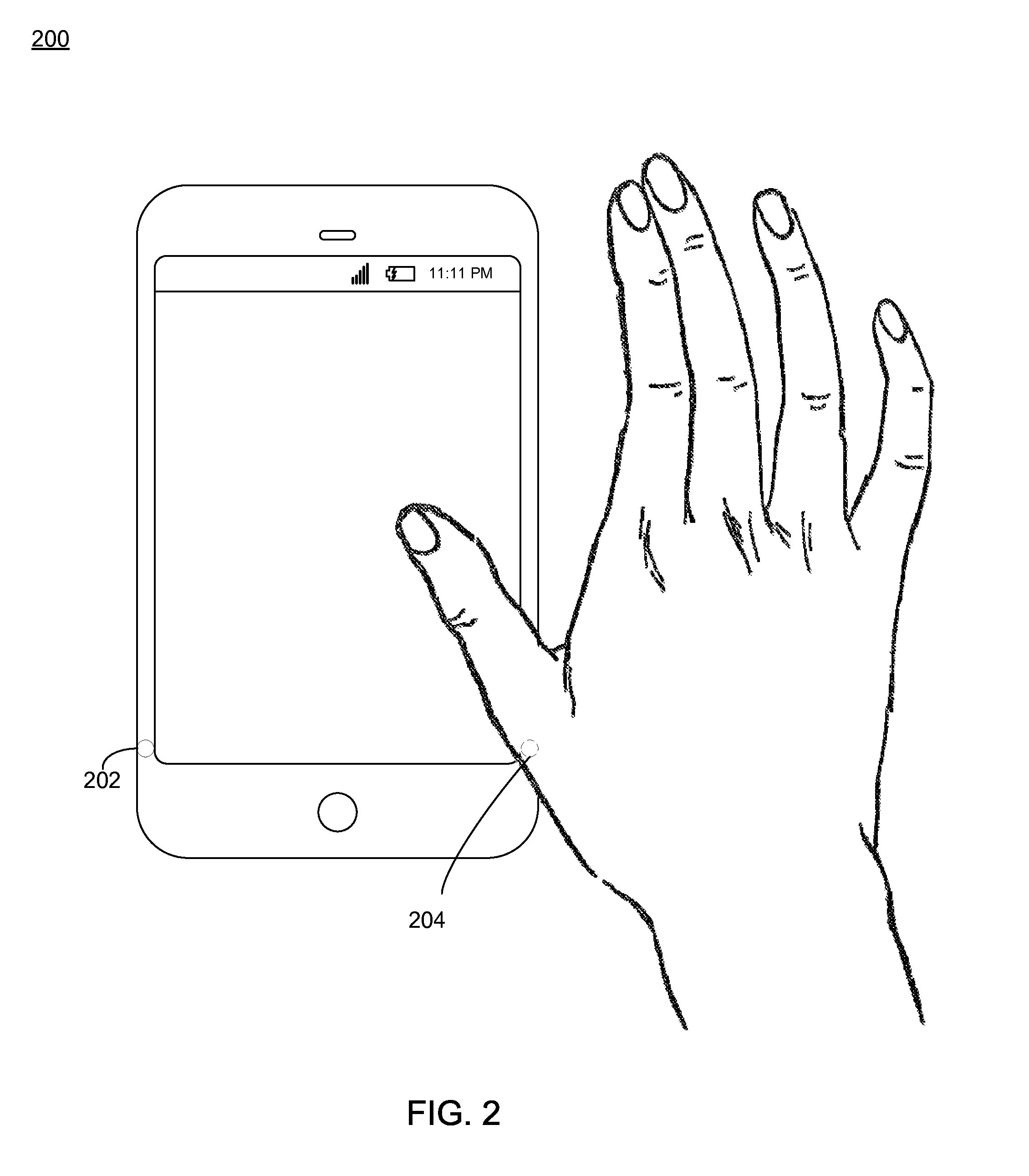
[0023]Embodiments provided herein are directed towards a microphone identification process 10 configured to detect an obstructed microphone in a multi-channel speech enhancement system. In the case of multi-channel speech enhancement a beamforming approach is commonly used. Here, the system may produce a poor output signal or fail completely if a microphone is covered, e.g., by the hand of the user. As expected, this risk increases at small hand-held devices like tablet-computers or mobile phones. If a covered microphone is detected the signal processing may be adjusted to achieve an enhanced output signal also in these critical situations.

[0024]In this way, if one microphone within a beamforming system is covered, e.g., by the hand of a user, the spatial filtering may not work correctly anymore and the output signal is not enhanced but rather impaired. This may be particularly true for adaptive beamforming as signal cancellation may occur and the desired speech signal is strongly a...


PUM


Abstract

Embodiments disclosed herein may include determining a signal parameter of a first microphone and a second microphone associated with a computing device. Embodiments may include generating a reference parameter based upon at least one of the parameter of the first microphone and the parameter of the second microphone. Embodiments may include adjusting a tolerance of at least one of the first microphone and the second microphone, based upon the reference parameter. Embodiments may include receiving, at the first microphone, a first speech signal, the first speech signal having a first speech signal magnitude and receiving, at the second microphone, a second speech signal, the second speech signal having a second speech signal magnitude. Embodiments may include comparing at least one of the first speech signal magnitude and the second speech signal magnitude with a third speech signal magnitude and detecting an obstructed microphone based upon the comparison.

Description

TECHNICAL FIELD[0001]This disclosure relates to signal processing systems and, more particularly, to a method for identifying one or more obstructed microphones associated with the signal processing system.BACKGROUND[0002]Microphones used in signal processing systems often have non-uniform characteristics. For example, the microphones in a hands-free voice command or communication system in an automobile may detect the same speech signal, but nonetheless produce very different microphone output signals. Non-uniform microphone characteristics may result from variations in the microphone fabrication process, from changes arising in the microphones from age, use, temperature, humidity, altitude, or from other factors. Non-uniform microphone characteristics may result in non-uniform frequency response between microphones, reduced signal strength and sampling accuracy, inconsistent sampling of sound signals, and generally reduced system performance. Occasionally, a non-uniform microphone...

Claims


Application Information

Patent Timeline
Patent Type & Authority Applications(United States)
IPC IPC(8): H04R3/00
CPCH04R3/00H04R2499/11H04R2430/23H04R3/005H04R2430/03H04M1/03H04M1/6008G06F3/165
Inventor MATHEJA, TIMOBUCK, MARKUS
Owner CERENCE OPERATING CO
Why Eureka
Try Eureka