Three-dimensional image acquisition system

Inactive Publication Date: 2016-02-25
VIT
View PDF5 Cites 6 Cited by
  • Summary
  • Abstract
  • Description
  • Claims
  • Application Information

AI Technical Summary

Benefits of technology

[0008]An object of an embodiment is to provide a three-dimensional image acquisition device implying fast a

Problems solved by technology

A disadvantage of known devices is that, according to the three-dimensional structure of the scene to be obs

Method used


Image

  • Three-dimensional image acquisition system
  • Three-dimensional image acquisition system
  • Three-dimensional image acquisition system

Examples


Embodiment Construction

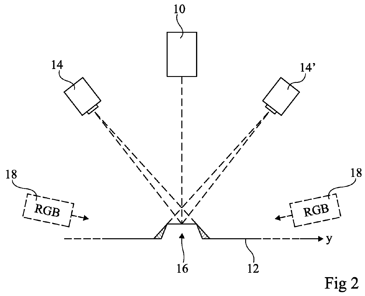
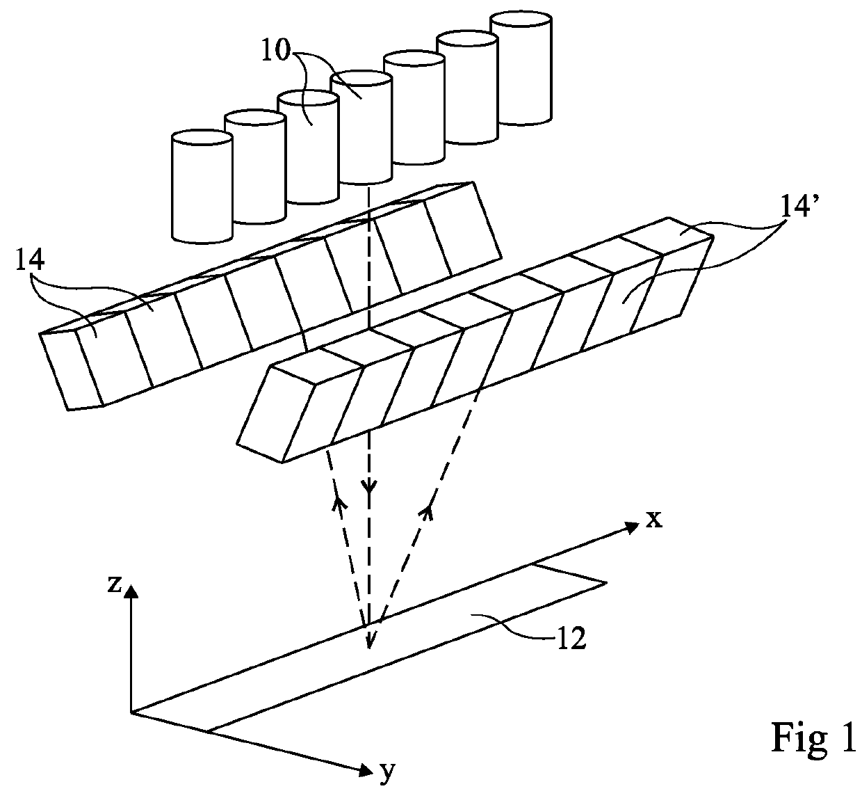
[0029]FIG. 1 is a simplified perspective view of a three-dimensional image acquisition device such as described in European patent application published under number EP 2413095. FIG. 2 is a side view of the device of FIG. 1, positioned above a scene in relief.

[0030]The device of FIG. 1 comprises a plurality of projectors 10 placed vertically above a three-dimensional scene 12. Scene 12, or observation plane, extends along two axes x and y, and projectors 10 have projection axes in this example parallel to a third axis z. Scene 12 is provided to be displaced, between each image acquisition step, along the direction of axis y.

[0031]Projectors 10 are aligned with one another along axis x, and their projection axes define a plane (to within the projector alignment) which will be called projector plane hereafter. Projectors 10 are directed towards scene 12. It should be noted that projectors 10 may be provided so that their beams slightly overlap at the level of scene 12.

[0032]Two groups...


PUM


Abstract

A three-dimensional image acquisition system including: at least two projectors aligned in a direction and suitable for illuminating a scene, the projection axes of the projectors defining a plane for each projector, and being turned toward the scene. A first and second camera are placed on one side of said plane, and a third and fourth camera placed on the other side of said plane. The optical axis of the first and second cameras form, with said plane, a different first and second angle, respectively, and the optical axis of the third and fourth cameras form, with said plane, a different third and fourth angle, respectively.

Description

[0001]The present patent application claims the priority benefit of French patent application FR13 / 53170 which is herein incorporated by reference.BACKGROUND[0002]The present disclosure generally relates to optical inspection systems and, more specifically, to three-dimensional image determination systems intended for the on-line analysis of objects, particularly of electronic circuits. The disclosure more specifically relates to such an acquisition system which rapidly and efficiently processes the obtained information.DISCUSSION OF THE RELATED ART[0003]Three-dimensional image acquisition systems are known. For example, in the field of printed circuit board inspection, it is known to illuminate a scene by means of one or a plurality of pattern projectors positioned above the scene and, by means of one or of two monochrome or color cameras, to detect the shape of the patterns obtained on the three-dimensional scene. An image processing is then carried out to reconstruct the three-di...

Claims


Application Information

Patent Timeline
IPC IPC(8): H04N13/02G01B11/245G01B11/25H04N5/225
CPCH04N13/0242H04N5/2256G01B11/245G01B11/25G01B11/2527G01B11/2545H04N13/243H04N23/56
Inventor PERRIOLLAT, MATHIEULAN, KE-HUA
Owner VIT
Why Eureka
Try Eureka