Liquid Crystal Display and Optical Compensation Method Therefor

a liquid crystal display and optical compensation technology, applied in the field of liquid crystal display, can solve the problems of serious light leakage, and achieve the effect of poor contrast of large viewing angle and small viewing angle rang

Inactive Publication Date: 2016-03-03
TCL CHINA STAR OPTOELECTRONICS TECH CO LTD
View PDF3 Cites 3 Cited by
  • Summary
  • Abstract
  • Description
  • Claims
  • Application Information

AI Technical Summary

Benefits of technology

[0008]A primary object of the present invention is to provide a liquid crystal display and an optical compensation method therefor, which are used to solve the problem of using the compensation value of the traditional A-Plate and C-Plate to cause the serious light leakage when watching at a large viewing angle in a dark state, the contrast of the large viewing angle becomes poor and the range of the viewing angle is actual small.
[0034]The present invention reduces the dark-state light leakage of a large viewing angle by adjusting the compensation values of the A-Plate and the C-Plate in the liquid crystal display. The implementation of the present invention can effectively increase the contract and resolution of the viewing angle (non-horizontal, large viewing angle of vertical pretwist angle).

Problems solved by technology

As shown in FIG. 1 and FIG. 2, when the compensation values of A-Plate and C-Plate are used, a serious light leakage may be generated if watching at a large viewing angle in a dark state, wherein the contrast of the large viewing angle becomes poor and the range of the viewing angle is actually small.

Method used


Image

  • Liquid Crystal Display and Optical Compensation Method Therefor
  • Liquid Crystal Display and Optical Compensation Method Therefor
  • Liquid Crystal Display and Optical Compensation Method Therefor

Examples


first embodiment

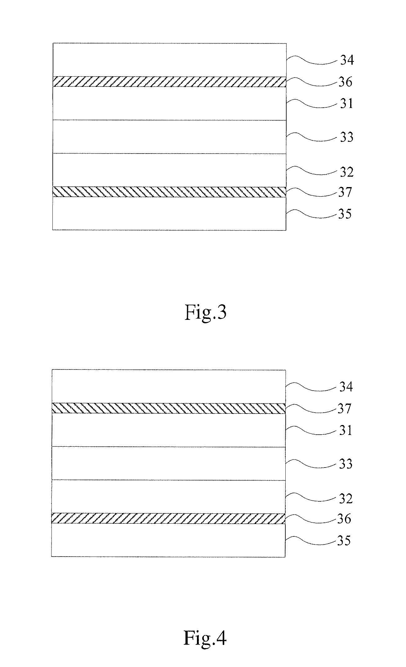
[0053]Referring to FIG. 3, in the first embodiment, the liquid crystal display comprises a first substrate 31, a second substrate 32, a liquid crystal layer 33, a first polarizing film 34, a second polarizing film 35, an uniaxial positive birefringence A-compensation film (A-Plate) 36 and an uniaxial negative birefringence C-compensation film (C-Plate) 37. The liquid crystal layer 33 is disposed between the first substrate 31 and the second substrate 32, the first polarizing film 34 is disposed on an outer side of the first substrate 31, and the second polarizing film 35 is disposed on an outer side of the second substrate 32.

[0054]In a specific implementation, the A-Plate 36 and the C-Plate 37 are disposed respectively on two opposite sides of the liquid crystal layer, and are disposed between the first substrate 31 and the first polarizing film 34 or disposed between the second substrate 32 and the second polarizing film 35.

[0055]For example, referring to FIG. 3, in the first embo...

second embodiment

[0056]Referring to FIG. 4, in a second embodiment, the A-Plate 36 is disposed between the second substrate 32 and the second polarizing film 35, and the C-Plate 37 is disposed between the first substrate 31 and the first polarizing film 34.

[0057]Otherwise, in other embodiments, the A-Plate 36 and the C-Plate 37 are disposed respectively on the same side of the liquid crystal layer and are disposed between the first substrate 31 and the first polarizing film 34 or disposed between the second substrate 32 and the second polarizing film 35.

third embodiment

[0058]Referring to FIG. 5, in a third embodiment, the A-Plate 36 and the C-Plate 37 are adhered to each other, and are disposed between the first substrate 31 and the first polarizing film 34.


PUM

PropertyMeasurementUnit
optical path differenceaaaaaaaaaa

Abstract

A liquid crystal display and an optical compensation method therefor are provided specifically for adjusting compensation values of an uniaxial positive birefringence A-compensation film (A-Plate) and an uniaxial negative birefringence C-compensation film (C-Plate) and particularly for controlling a valuing range of a compensation value (Rth) of the C-Plate, so as to reduce the dark-state light leakage by adjusting the compensation values of two types of the compensation film. Thus, the present invention can reduce the dark-state light leakage of a large viewing angle and increase the contrast and definition of the large viewing angle.

Description

FIELD OF THE INVENTION[0001]The present invention relates to a field of technology of liquid crystal display and more particularly to a liquid crystal display and an optical compensation method therefor.BACKGROUND OF THE INVENTION[0002]The quality requirement of the liquid crystal display (LCD) panel is higher and higher with the growing popularity of the liquid crystal display panel. For example, with the increasing of the viewing angle of a thin film transistor LCD (TFT-LCD), the contrast and resolution of the screen thereof are gradually decreased. It is due to a result that a birefringence of the liquid crystal molecule in the liquid crystal layer is changed with the variation of the viewing angle. The dark-state light leakage can be effectively reduced by a wide viewing angle compensation film. A contrast of the screen can be considerably increased within a specific viewing angle.[0003]The compensation principle of the compensation film is generally to correct the phase differe...

Claims


Application Information

Patent Timeline
Patent Type & Authority Applications(United States)
IPC IPC(8): G02F1/13363G02F1/1335
CPCG02F1/13363G02F2413/11G02F1/133634G02F1/133528G02B5/3083G02F2413/02
Inventor KANG, CHIHTSUNGHAI, BO
Owner TCL CHINA STAR OPTOELECTRONICS TECH CO LTD
Why Eureka
Try Eureka